Maintaining equipment used for outdoor care can be a complex task, especially when trying to ensure optimal performance. Understanding the different components that make up these machines is crucial for ensuring smooth operation and longevity. Whether you’re dealing with small mechanical elements or larger assemblies, having a clear understanding of how each part contributes to the overall function is vital.
In this section, we’ll dive into the intricacies of mechanical layouts, offering a detailed look at how various systems work together. From the engine to the cutting mechanisms, each aspect plays a unique role in delivering the desired outcome in yard maintenance. By familiarizing yourself with these elements, you’ll be better equipped to handle repairs and routine upkeep.
Additionally, we’ll provide insights into how to identify individual components and their placement within the overall structure. This knowledge can help prevent costly mistakes, reduce downtime, and ensure that your equipment operates efficiently for years to come.
Overview of Key Components
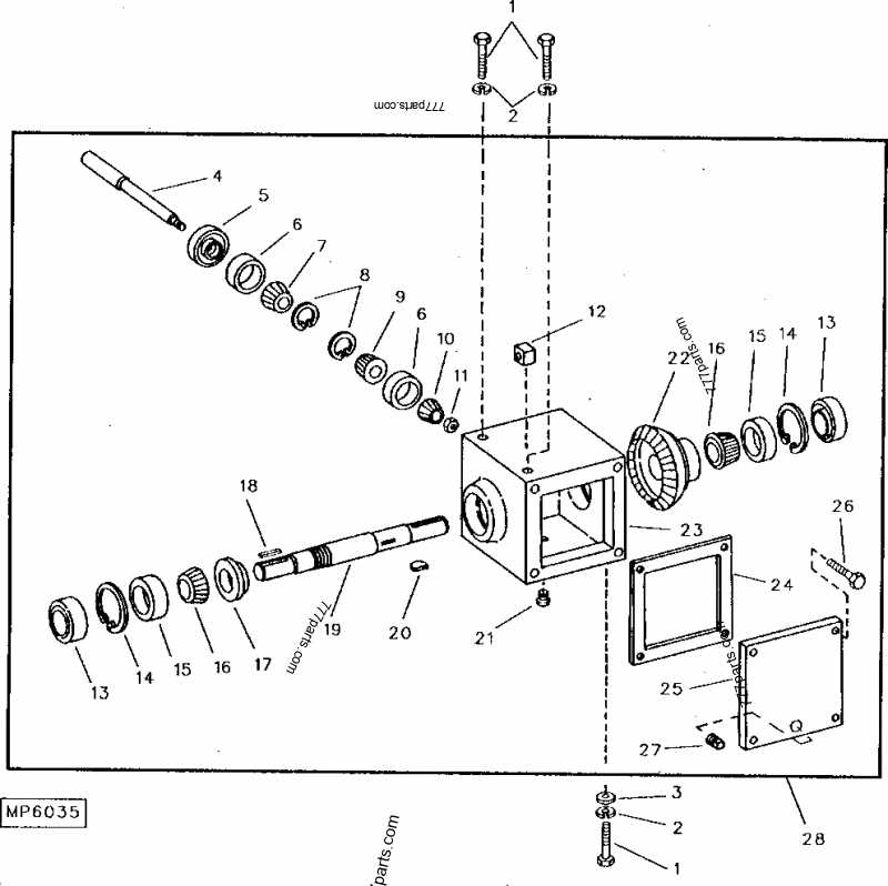
The essential mechanical elements within this equipment are designed to ensure smooth functionality and longevity. Understanding how each component interacts with the others can help in maintaining the system’s efficiency. By familiarizing yourself with the primary structures, you can better identify areas requiring attention or possible upgrades.
Engine Assembly
The engine assembly forms the core of the system, responsible for powering the entire machine. It includes a variety of intricate parts that work together to deliver consistent performance. Regular inspection of this assembly is vital for optimal operation and to prevent potential breakdowns.
Steering Mechanism

The steering mechanism ensures precise control and maneuverability. This system consists of both mechanical and hydraulic components, allowing the operator to navigate various terrains with ease. Proper upkeep of these elements will guarantee smooth and responsive handling over time.
Understanding the Drive System Layout
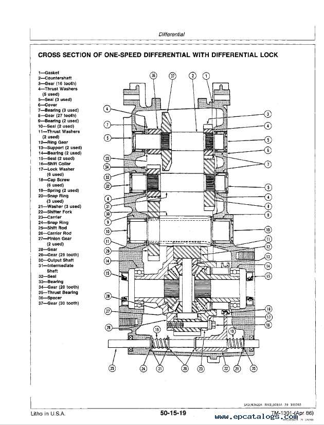
The drive system layout is a crucial aspect to explore when assessing the overall functionality of any vehicle. It involves the arrangement of components that work together to ensure smooth and efficient movement. Knowing how these elements interact can help in understanding both the performance and potential maintenance needs.
The core of this system consists of interconnected parts that transmit power from the engine to the wheels, allowing motion. Each element plays a significant role in this transfer, and proper alignment is essential for optimal operation.
- Engine Connection: The power begins its journey here, moving from the engine to the transmission.
- Transmission: This component manages the power distribution to ensure the correct speed and torque.
- Axle Assembly: The axle transfers power from the transmission to the wheels, enabling forward and reverse motion.
- Wheel Components: These final elements of the system directly engage with the ground, translating the power into movement.
By understanding each part and how they work together, it’s possible to diagnose issues more effectively and ensure consistent performance of the drive system.
Engine Parts and Their Functions
The inner workings of any engine rely on a variety of components, each contributing to the overall performance and efficiency. These essential elements are designed to ensure smooth operation and optimal power output. Understanding how these components work together is key to maintaining the engine’s longevity and reliability.
| Component | Function | ||||||||||
|---|---|---|---|---|---|---|---|---|---|---|---|
| Cylinder | Houses the piston and is the space where fuel combustion occurs, generating energy. | ||||||||||
| Piston | Moves within the cylinder, converting the energy from combustion into mechanical motion. | ||||||||||
| Crankshaft | Transforms the linear motion of the pistons into rotational motion, driving the machine. | ||||||||||
| Camshaft | Controls the opening and closing of valves, ensuring the correct timing of fuel intake and exhaust release. | ||||||||||
| Valves | Regulate the flow of fuel and air into the cylinder and
Hydraulic System Configuration
The hydraulic mechanism plays a crucial role in optimizing the machine’s performance by enabling fluid power transfer to various components. This section explores the fundamental structure and operation of the hydraulic system, focusing on its key elements and how they work together to deliver efficient power distribution and control. Below are the main components and their roles within the hydraulic setup:
This configuration allows for smooth, controlled movement and effective energy transfer, enhancing the overall functionality of the machine’s key processes. Electrical System OverviewThe electrical system is responsible for powering various components, ensuring optimal performance and functionality. This section provides a general understanding of how power is distributed and managed across the equipment, focusing on essential elements that contribute to efficient operation. Main Components
The assembly of the cutting platform is a crucial component in the maintenance and functionality of outdoor equipment. Understanding how each element fits together can enhance efficiency and prolong the lifespan of the machinery. This section will provide an overview of the primary components involved in constructing the mowing platform. Key components include:
Each of these parts plays a vital role in the overall performance of the cutting unit. Proper assembly and maintenance ensure optimal operation, enabling the machine to deliver precise and consistent results during use. For effective assembly, follow these guidelines:
Regular inspection and maintenance of the assembly are essential to prevent wear and tear, ensuring the longevity and effectiveness of the equipment. Fuel System BreakdownThis section provides an overview of the components and functionality of the fuel delivery mechanism. Understanding the intricacies of this system is essential for optimal operation and maintenance. Proper fuel management ensures efficiency and longevity of the machinery, preventing issues that can arise from inadequate fuel supply or contamination. Key ComponentsThe fuel delivery mechanism consists of several critical elements that work in unison to ensure the engine receives the necessary fuel for combustion. These components include the fuel tank, pump, filter, and injectors. Each part plays a vital role in the overall performance and reliability of the system. Functionality OverviewThe fuel system operates by drawing fuel from the tank through a pump, which then filters the fuel to remove impurities before it reaches the engine. This process is crucial for maintaining engine performance and preventing damage.
Control Panel ComponentsThe control interface of any machinery is essential for efficient operation. It serves as the central hub for user interaction, allowing for the monitoring and management of various functions. Understanding the individual elements that comprise this interface is crucial for effective usage and troubleshooting. Key ElementsAmong the fundamental components are various switches and indicators that provide vital information regarding the equipment’s status. These elements ensure that users can easily navigate through different settings and respond promptly to any alerts. Familiarity with these features enhances overall operational safety and effectiveness. Functional Features
In addition to basic controls, advanced functionalities such as digital displays and customizable settings play a significant role. These features enable users to tailor the experience to specific needs, enhancing both comfort and productivity. Moreover, regular maintenance of these components is essential to ensure reliability and longevity. Steering and Transmission LinkageThe steering and transmission linkage system is a critical component in ensuring efficient control and maneuverability of the equipment. This system comprises various elements that work together to translate the operator’s input into precise movements, enabling seamless operation across diverse terrains. Key components of this system include:
Maintaining the integrity of these components is essential for optimal performance. Regular inspections and timely replacements can prevent potential issues and ensure the longevity of the machinery. Proper adjustments to the linkage can also enhance responsiveness and driving comfort. In summary, the steering and transmission linkage system plays a vital role in the overall functionality of the equipment. Understanding its components and maintenance needs is crucial for operators aiming to achieve efficient and reliable performance. Blade and Cutting MechanismThe cutting apparatus is a crucial element in achieving efficient performance and precise results during operation. Understanding its design and functionality can enhance the user experience and maintenance of the machinery. This section delves into the various components and features associated with the cutting mechanism:
Proper maintenance of the cutting assembly is vital for optimal performance. Regular checks and adjustments can prevent wear and prolong the lifespan of the equipment. Key maintenance practices include:
By familiarizing oneself with these aspects, operators can ensure their cutting equipment remains efficient and reliable throughout its use. Maintenance Tips for Long-Term DurabilityEnsuring the longevity of machinery requires consistent attention and care. Regular maintenance practices not only enhance performance but also extend the operational lifespan of the equipment. Implementing a few straightforward strategies can yield significant benefits over time. 1. Regular Inspections: Conduct frequent evaluations to identify wear and tear. Checking components for signs of damage or corrosion can help prevent larger issues down the line. 2. Cleanliness is Key: Keep the equipment free from dirt and debris. Regular cleaning prevents buildup that can lead to malfunctions and ensures all parts function smoothly. 3. Lubrication: Apply appropriate lubricants to moving parts. Proper lubrication minimizes friction and wear, which is crucial for maintaining efficiency. 4. Timely Replacements: Replace worn-out components as soon as they show signs of deterioration. Proactive replacement reduces the risk of unexpected breakdowns. 5. Follow Manufacturer Guidelines: Adhere to the recommended maintenance schedule provided by the manufacturer. This ensures all maintenance tasks are completed at the appropriate intervals for optimal performance. 6. Training and Awareness: Educate operators on proper handling and maintenance practices. Knowledgeable users can help detect issues early and perform basic maintenance tasks effectively. By following these essential tips, the machinery will not only perform better but also enjoy an extended life, reducing the need for costly repairs and replacements. |

