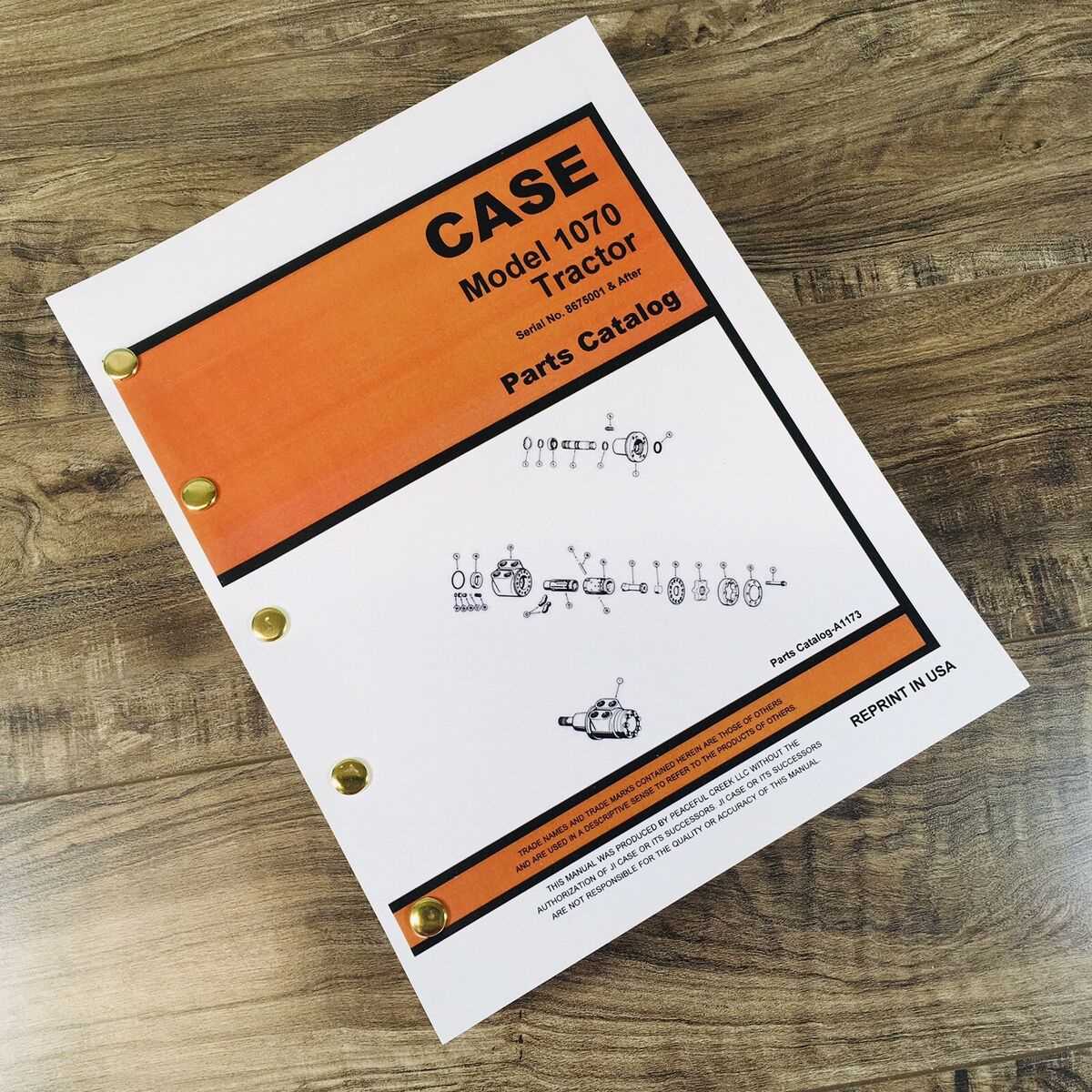
In the realm of industrial equipment, having a clear grasp of the essential elements that make up these complex machines is crucial for effective maintenance and operation. A thorough exploration of these components not only aids in troubleshooting but also enhances overall efficiency.
Visual representations play a significant role in grasping the intricate relationships between various sections of machinery. By breaking down the structure into understandable segments, operators can quickly identify potential issues and address them proactively.
For anyone involved in the management or servicing of heavy-duty machines, the ability to navigate through these intricate layouts is the ultimate key to success. With the right tools and knowledge, you can ensure optimal performance and longevity of your equipment.
Understanding Case 1070 Parts Diagram
This section aims to explore the essential components and their arrangement in a specific machine model, enhancing your familiarity with its operational structure.
When you analyze the layout, consider the following key aspects:
- Functionality: Each element serves a distinct role in the overall system.
- Interconnections: Understanding how parts interact can improve maintenance and repairs.
- Accessibility: Knowing where components are located aids in troubleshooting and efficiency.
By delving into these elements, you can gain a clearer insight into the assembly and enhance your operational knowledge.
Importance of Parts Diagrams
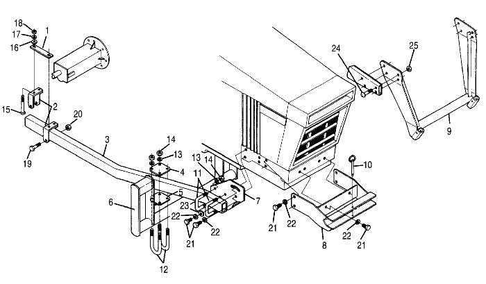
Understanding the intricacies of machinery relies heavily on visual representations that illustrate the individual components and their relationships. Such depictions serve as essential tools for technicians and engineers, providing clarity and enabling efficient problem-solving.
Facilitating Maintenance and Repair
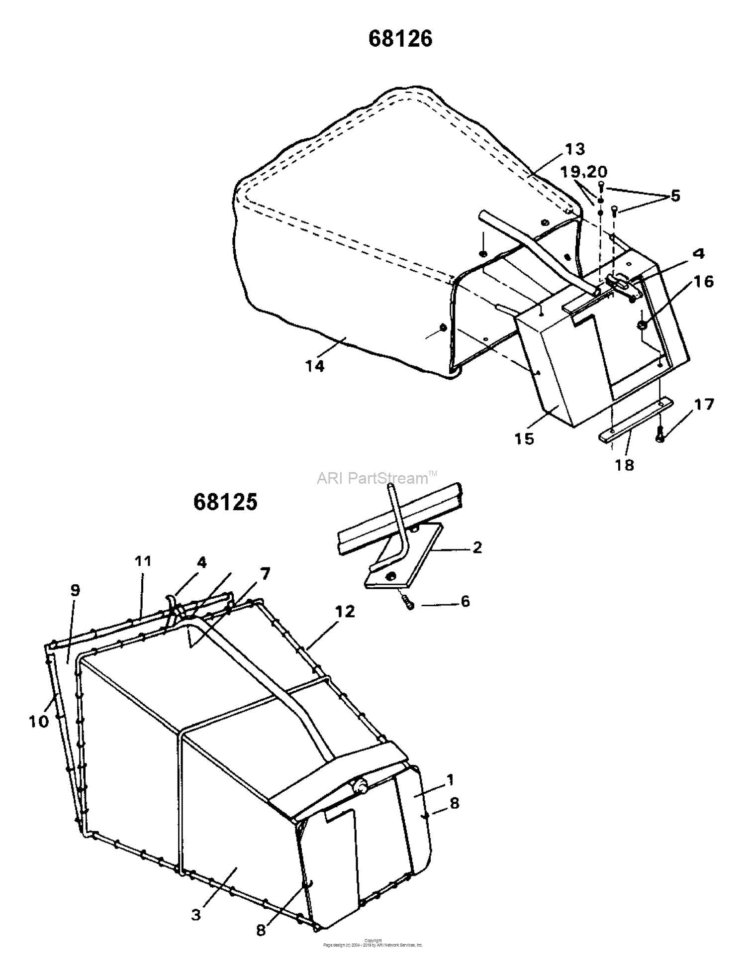
Accurate visual guides simplify the process of maintenance and repair by allowing users to identify specific elements quickly. This efficiency minimizes downtime and enhances productivity, ensuring that equipment operates smoothly. Moreover, having a clear reference reduces the likelihood of errors during reassembly.
Enhancing Communication
Visual representations foster better communication among team members. When discussing modifications or repairs, having a common reference point aids in conveying ideas clearly, ensuring everyone is aligned on the task at hand. This clarity is especially crucial in complex projects involving multiple stakeholders.
| Benefits | Description |
|---|---|
| Improved Accuracy | Reduces the chances of mistakes during repairs. |
| Time Efficiency | Accelerates the identification of components. |
| Enhanced Collaboration | Facilitates clear communication among team members. |
| Informed Decision-Making | Provides valuable insights for modifications and upgrades. |
Overview of Case 1070 Components
This section provides a comprehensive look at the various elements that comprise this powerful machinery, emphasizing their interconnectivity and functionality. Each component plays a crucial role in the overall performance, contributing to efficiency and reliability.
Key Functional Elements
Among the essential elements are the engine assembly, transmission system, and hydraulic components. These parts work together to ensure optimal operation, facilitating smooth movements and effective power delivery.
Maintenance and Upkeep
Regular inspection of these vital components is critical for longevity. Timely replacements and adjustments can prevent breakdowns, ensuring that the machinery remains in top condition for ultimate productivity.
How to Read the Diagram
Understanding technical illustrations is essential for effective maintenance and repair tasks. These visual representations serve as a guide, allowing users to identify various components and their relationships within a system. Grasping the layout and symbols used can significantly enhance your ability to work efficiently and accurately.
Start by familiarizing yourself with the overall structure. Most illustrations will feature a legend or key that explains the symbols and lines. This is crucial for deciphering the information presented. Pay close attention to labels and numbering, as these often indicate specific parts or functions.
Next, observe how different elements are connected. Arrows and lines typically indicate flow or relationships, guiding you through the system’s operation. Identifying the main components first can provide context for the smaller parts, making it easier to understand their roles.
Lastly, take your time when analyzing the illustration. A methodical approach allows for a deeper understanding of how everything works together, ensuring that you can troubleshoot or replace components with confidence.
Common Issues with Case 1070 Parts
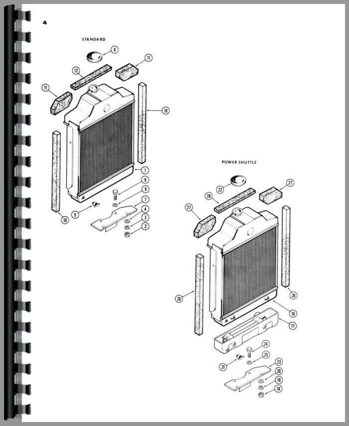
In the realm of machinery maintenance, certain components often present challenges that can affect overall performance. Understanding these frequent complications is crucial for ensuring longevity and efficiency. Operators frequently encounter wear and tear, leading to malfunctions and requiring timely intervention.
One prevalent concern involves hydraulic systems, where leaks can compromise functionality. Insufficient lubrication can result in increased friction, accelerating deterioration. Additionally, electrical failures may arise due to corroded connections, hindering operation. Routine inspections are essential to identify these issues early and mitigate further damage.
Moreover, operators should be aware of the potential for misalignment in various assemblies, which can lead to abnormal wear patterns. Regular maintenance practices and adhering to recommended service schedules are vital to minimize these risks and maintain optimal performance.
Maintenance Tips for Case 1070
Regular upkeep is essential for ensuring the longevity and efficiency of your machinery. Adhering to a consistent maintenance routine not only enhances performance but also minimizes the risk of unexpected breakdowns. Here are some valuable recommendations to keep your equipment running smoothly.
- Routine Inspections: Schedule frequent checks to identify wear and tear early. Pay special attention to hydraulic systems and engine components.
- Fluid Levels: Regularly monitor and maintain proper fluid levels, including oil, coolant, and hydraulic fluids. Replace them according to the manufacturer’s guidelines.
- Filter Changes: Replace air and fuel filters at recommended intervals to ensure optimal performance and prevent contaminants from damaging the engine.
- Clean Components: Keep external surfaces clean to avoid buildup of dirt and debris, which can affect cooling and overall functionality.
By implementing these maintenance strategies, you can significantly extend the operational life of your machinery and enhance its overall performance.
Where to Find Replacement Parts
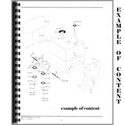
Locating suitable components for your machinery can enhance its performance and longevity. Various avenues exist to acquire these essential items, ensuring that your equipment remains operational.
- Manufacturer’s Website: Start by visiting the official site, where you can often find a dedicated section for components and accessories.
- Authorized Dealers: Connect with local distributors who specialize in equipment and can provide genuine replacements.
- Online Marketplaces: Explore platforms that offer a wide range of options, including new and refurbished items.
- Specialized Retailers: Look for stores that focus specifically on machinery supplies, often offering expertise and a broad selection.
- Salvage Yards: Consider checking out yards that specialize in used equipment, where you may find valuable components at a lower cost.
By exploring these resources, you can effectively secure the necessary items to maintain your machinery in peak condition.
Comparing Case 1070 to Other Models
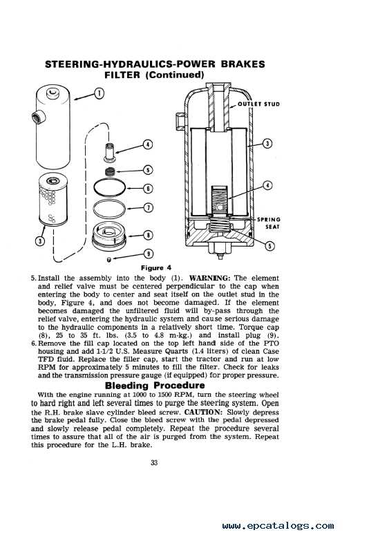
This section explores the distinctions and similarities between a specific agricultural machinery model and its counterparts. By analyzing various features, capabilities, and overall performance, we can gain insight into how this model stands within its category and what sets it apart.
Performance Metrics
When evaluating efficiency and power output, it’s essential to consider the engine specifications and operational capacity. Comparisons reveal varying torque levels and horsepower ratings, which influence productivity in diverse farming tasks.
User Experience
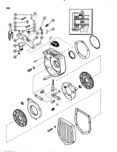
Another significant aspect is user-friendliness, including controls and comfort during operation. Feedback from operators highlights differences in ergonomics and ease of maintenance, which can affect long-term satisfaction and functionality.
Assembly Process Using the Diagram
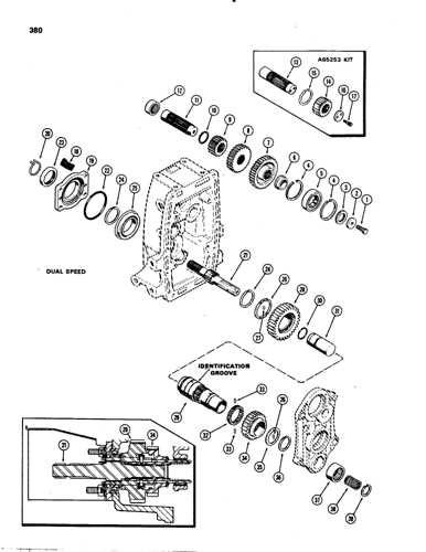
The assembly procedure is a crucial aspect that requires careful attention to detail and a clear understanding of each component’s role. By following a structured visual representation, individuals can ensure a systematic approach to putting together the various elements efficiently.
Key Steps in the Assembly
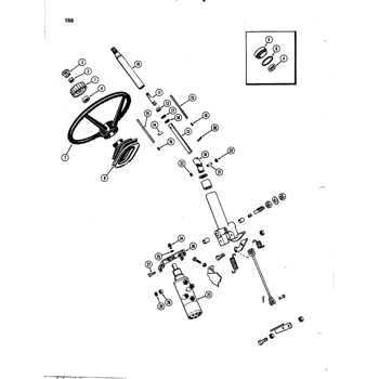
- Gather all components needed for the assembly.
- Refer to the visual representation to understand the arrangement.
- Start with the foundational elements, ensuring stability.
- Sequentially add each part, checking for alignment.
- Utilize the appropriate tools for secure connections.
- Conduct a final inspection for any discrepancies.
Benefits of Following a Visual Guide
- Enhances accuracy in the assembly process.
- Reduces the likelihood of errors.
- Increases efficiency and speed.
- Facilitates easier troubleshooting if issues arise.
Tips for Troubleshooting Problems
Tackling mechanical issues requires a systematic approach to identify and resolve faults effectively. Understanding the common challenges can streamline the process and lead to quicker solutions.
- Start with a visual inspection to identify any obvious signs of wear or damage.
- Check all connections and wiring for any loose or frayed parts.
- Consult the manual for troubleshooting guidelines specific to your model.
Once you have gathered preliminary information, consider the following steps:
- Test each component individually to isolate the problem area.
- Look for any unusual noises or performance issues during operation.
- Document your findings to track patterns or recurring issues.
By following these strategies, you can delve deeper into the problem and enhance your understanding of the overall system performance.
Frequently Asked Questions about Case 1070
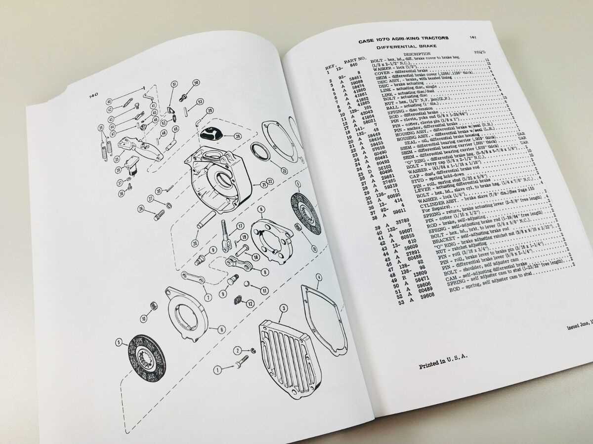
This section addresses common inquiries regarding a specific model, focusing on essential components and their functions. Understanding these elements can enhance the experience for users and technicians alike.
- What is the primary function of the main components?
The main components work together to ensure efficient operation, delivering power and performance for various tasks.
- How do I identify worn-out parts?
Signs of wear may include unusual noises, decreased efficiency, and visible damage.
- Where can I find replacement components?
Replacement parts can be sourced from authorized dealers or trusted aftermarket suppliers.
- What maintenance is recommended?
Regular checks, lubrication, and timely replacements are crucial for optimal performance.
- Are there common issues to be aware of?
Users often report issues such as overheating, hydraulic failures, and electrical malfunctions.