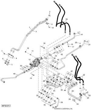
Understanding the configuration of machinery elements is crucial for ensuring smooth operation and efficient maintenance. This section delves into the intricate details of how these components interact to deliver optimal performance. By analyzing their layout, users can gain a clearer perspective on how to address potential issues or upgrades effectively.
Each piece of equipment relies on a specific setup that defines its functionality and overall reliability. Highlighting the precise arrangement of various segments helps technicians and enthusiasts alike to familiarize themselves with the machine’s structure. Such knowledge is invaluable for troubleshooting, ensuring that every detail is in place for seamless operations.
With a comprehensive grasp of these setups, one can perform repairs or replacements with confidence. This detailed analysis not only aids in identifying specific elements but also offers insight into the machine’s design principles, allowing for more informed decisions when it comes to maintenance and enhancement.
 tags: Exploring John Deere 110 Component Layout”>
The focus of this section is to offer a detailed overview of the essential components that make up this versatile machinery. By examining the layout of each element, the goal is to provide clarity on how these pieces interact to form a cohesive unit. This exploration will guide you through the structural arrangement, emphasizing the significance of each part within the overall system. Understanding the organization of these elements is key to both maintenance and efficient operation.
Each segment will delve into a specific aspect of the equipment, highlighting the practical role of various elements. This approach ensures a comprehensive grasp of the mechanical structure, which is crucial for anyone looking to optimize the usage or upkeep of this equipment. By breaking down the layout into easily understandable sections, we aim to simplify the complexities of the assembly for users and technicians alike.
Hydraulic System Overview and Analysis
The hydraulic mechanism serves as a fundamental component in many heavy-duty machines, driving a range of essential operations. By converting fluid pressure into mechanical energy, this system ensures the smooth and efficient performance of various tasks, reducing the need for manual effort. Understanding its structure and functionality is key to maintaining peak operational efficiency.
- Pumps: These elements generate the force needed to propel the fluid through the circuit, setting the system’s overall motion in action.
- Valves: Regulating the flow and pressure within the hydraulic network, valves play a crucial role in directing the movement and speed of the actuators.
- Cylinders: Acting as the power transmitters, cylinders convert the fluid’s hydraulic energy into linear motion, enabling the machine’s physical actions.
A thorough analysis of these components not only highlights their individual roles but also their interdependence in achieving precise and reliable machine performance. Regular inspection and maintenance are vital to prevent inefficiencies and ensure the longevity of the system.
Engine Assembly Breakdown
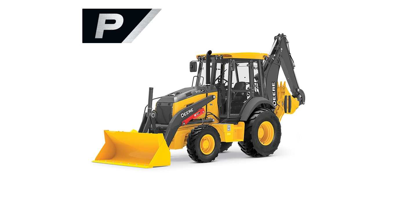
Understanding the structure and components of the engine system is crucial for efficient maintenance and repair. This section provides a detailed overview of the various elements that come together to form the engine’s core assembly, highlighting their roles and connections.
| Component | Description | Function |
|---|---|---|
| Cylinder Block | The main housing for the engine’s moving parts. | Acts as the foundation, holding cylinders and internal components in place. |
| Piston | A cylindrical part that moves within the chamber. | Transfers force from expanding gases to the crankshaft, generating power. |
| Crankshaft | A rotating shaft located at the base of the engine. | Converts the linear motion of pistons into rotational energy. |
| Camshaft | A shaft equipped with cams that operate the valves. | Controls the timing of valve operations to optimize engine performance. |
| Timing Belt | A belt connecting the crankshaft and camshaft. | Synchronizes the movement of engine components to ensure proper operation. |
Transmission System Components

The transmission setup in heavy machinery plays a critical role in managing power flow between the engine and the drivetrain. Understanding its fundamental elements is essential for diagnosing issues or enhancing performance. This section provides an overview of the core components involved in this mechanism.
Key Elements of the Transmission Assembly
The transmission system consists of several integral parts that work together to ensure smooth operation. These components regulate the speed and torque, adjusting to varying load conditions and driving requirements. Below is a breakdown of the primary elements found in this setup:
| Component | Function |
|---|---|
| Clutch Assembly | Engages and disengages the engine from the transmission to control power flow. |
| Gearbox | Adjusts the speed and torque by shifting between different gears based on operational needs. |
| Hydraulic System | Facilitates the smooth transition between gears, reducing wear and enhancing responsiveness. |
Maintenance and Inspection Tips
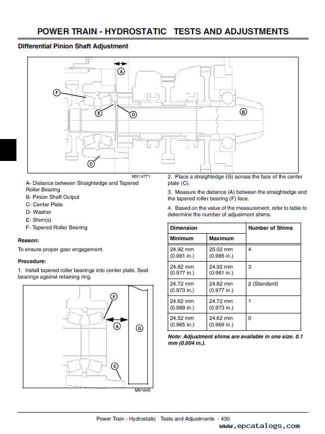
Regular inspection of the transmission components is crucial for optimal performance and longevity. Checking fluid levels, inspecting for leaks, and ensuring proper lubrication can prevent significant issues. Timely maintenance not only improves efficiency but also extends the lifespan of the machinery.
Detailed View of Control Levers
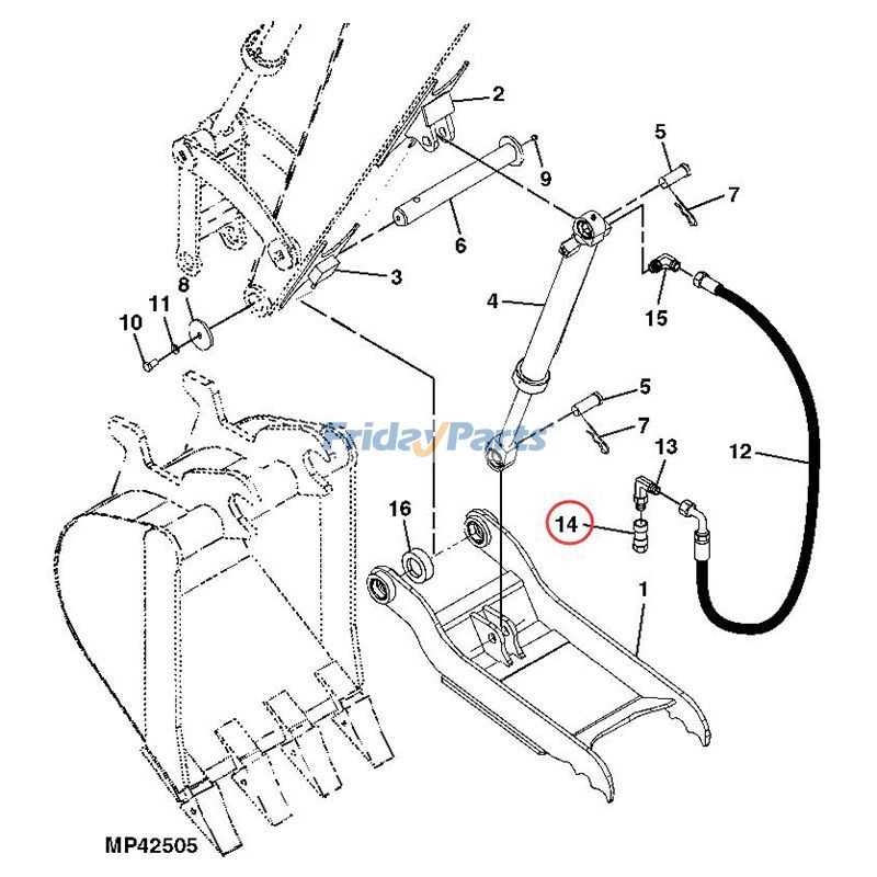
Understanding the configuration and functionality of the control handles is crucial for efficient machinery operation. This section explores the layout of these essential components, providing insights into their roles and how they contribute to precise maneuvering and task execution.
Primary Control Functions
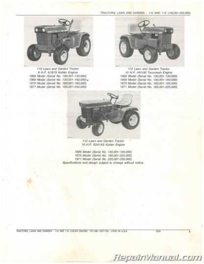
The control handles are designed to offer seamless manipulation of the equipment’s movements. Each lever corresponds to a specific action, enabling the operator to control various mechanisms with accuracy. By mastering these controls, one can ensure smoother operation and reduce the risk of errors during tasks.
Lever Arrangement Overview
The arrangement of the control levers is structured to enhance the operator’s accessibility and ergonomic comfort. Below is a table summarizing the main functions assigned to each lever, making it easier to identify their purpose and optimize their use during different operations.
| Lever Position | Functionality | Operational Use |
|---|---|---|
| Left Lever | Controls vertical movement | Used for lifting or lowering actions |
| Right Lever | Manages horizontal movement | Adjusts side-to-side positioning |
| Auxiliary Lever | Engages additional attachments | Activates secondary tools or implements |
Electrical Circuit Structure
Understanding the design of an electrical circuit within heavy machinery is crucial for ensuring efficient operation and troubleshooting. The layout typically involves a network of interconnected components that work together to transmit and regulate power throughout the system.
Primary Components
The main elements of the circuit consist of wiring, relays, switches, and connectors, all designed to manage the electrical flow. These components must be precisely aligned to ensure that the machinery functions correctly and to prevent power disruptions.
Power Distribution
Power is distributed through various paths to reach essential modules. The circuit’s architecture is crafted to maintain a balanced energy flow, minimizing the risk of overloads and ensuring that each section receives the appropriate voltage.
Chassis Frame and Linkage Details
The structural integrity of the machine heavily relies on its core framework and connecting mechanisms. Understanding the design and connection points of these components is crucial for maintaining optimal performance and ensuring durability in demanding tasks.
Key Elements of the Framework
The main frame is designed to provide stability and support to the entire system. It serves as the backbone, distributing weight evenly and minimizing stress on critical areas. Proper assessment of the framework can help identify any signs of wear or misalignment that might affect overall functionality.
Linkage Assembly Overview
The linkage assembly plays a vital role in transferring movement and force between different sections of the equipment. This interconnected system of levers and pivots is built for precision, enhancing control during operations. Regular inspection of these linkages ensures they function smoothly and maintain their resilience against heavy loads.
Steering Mechanism Examination
The steering system plays a crucial role in the maneuverability of heavy machinery, enabling precise control and navigation. Understanding its components and functionality is essential for effective maintenance and troubleshooting. This section delves into the key elements that comprise this mechanism and how they interact to facilitate smooth operation.
Components Overview
At the heart of the steering assembly is the control unit, which directs hydraulic fluid to the steering cylinders. These cylinders convert hydraulic energy into mechanical motion, allowing for swift turns and adjustments. Additionally, the linkage system connects the steering wheel to the hydraulic components, ensuring responsive handling.
Common Issues and Solutions
Several challenges can arise within the steering mechanism, such as leaks in hydraulic lines or worn components that hinder performance. Regular inspections can help identify these issues early. Maintaining proper fluid levels and addressing any signs of wear can significantly enhance the longevity and reliability of the steering system.
Undercarriage Assembly Insights
The undercarriage assembly plays a crucial role in the functionality and stability of heavy machinery. Understanding its components and their interrelationships is essential for effective maintenance and repair. This section will delve into the various elements that constitute this vital structure.
Key components of the undercarriage assembly include:
- Tracks: Provide traction and mobility across different terrains.
- Rollers: Support the weight of the machinery and facilitate smooth movement.
- Sprockets: Engage with the tracks to drive the vehicle forward.
- Idlers: Help maintain track tension and guide the tracks around the rollers.
Each of these parts must work harmoniously to ensure optimal performance. Regular inspection and timely replacement of worn-out components can significantly enhance the longevity and efficiency of the machinery. Adhering to maintenance schedules is crucial for preventing operational disruptions and costly repairs.
Front Loader Parts Overview
This section provides a comprehensive look at the components of a front-end loader, highlighting their functionality and importance in various applications. Understanding these elements is crucial for effective maintenance and operation, ensuring the machine performs optimally in different tasks.
Key Components

The loader consists of several essential elements that work together to achieve efficient lifting and moving of materials. Each component plays a specific role in the loader’s overall performance and reliability.
| Component | Description |
|---|---|
| Bucket | The primary tool used for scooping and lifting materials. |
| Arm | This structure connects the bucket to the loader frame and facilitates movement. |
| Pivot Point | The axis around which the arm and bucket rotate, enabling lifting actions. |
| Hydraulic Cylinder | Acts as the driving force, controlling the movement of the arm and bucket. |
| Frame | The main structure that supports all other components and ensures stability. |
Maintenance Tips
Regular inspection and maintenance of these components are essential for the longevity and effectiveness of the loader. Ensuring that hydraulic systems are properly lubricated and free of leaks can prevent costly repairs and downtime.
Backhoe Arm Segment Layout
The configuration of the digging mechanism is crucial for effective excavation and maneuverability. Understanding the arrangement of its components helps ensure optimal performance and reliability during operations.
This segment consists of several key elements that work together to provide strength and flexibility:
- Upper Arm: The primary support structure that connects to the main frame.
- Bucket Linkage: A system that facilitates the attachment and detachment of various tools.
- Lower Arm: Extends the reach of the digging equipment, allowing deeper access to the ground.
- Bucket: The tool that performs the actual digging, available in various sizes for different tasks.
Each component plays a vital role in the overall functionality, ensuring the equipment can efficiently handle various excavation tasks.
For effective maintenance and repair, it’s essential to be familiar with the layout and specifications of these components. Proper knowledge can lead to enhanced durability and performance.
Maintenance Tips for Key Components
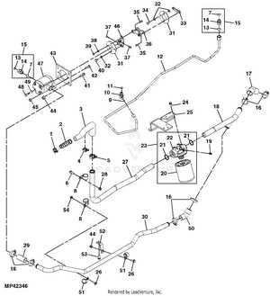
Proper upkeep of essential machinery elements is crucial for ensuring longevity and optimal performance. Regular inspections, timely replacements, and preventive measures can significantly enhance the reliability of equipment.
Here are some key practices to maintain vital components:
| Component | Maintenance Tip |
|---|---|
| Hydraulic System | Check fluid levels frequently and replace filters as per the manufacturer’s recommendations. |
| Engine | Regularly change oil and inspect belts for wear to prevent breakdowns. |
| Transmission | Monitor fluid levels and conduct periodic checks to avoid overheating and performance issues. |
| Brakes | Inspect brake pads and discs regularly for signs of wear and replace them as necessary. |
| Electrical System | Test battery connections and inspect wiring for damage to ensure reliable operation. |
By adhering to these maintenance tips, operators can prolong the lifespan of their machinery and minimize unexpected failures, ensuring efficient performance in various tasks.