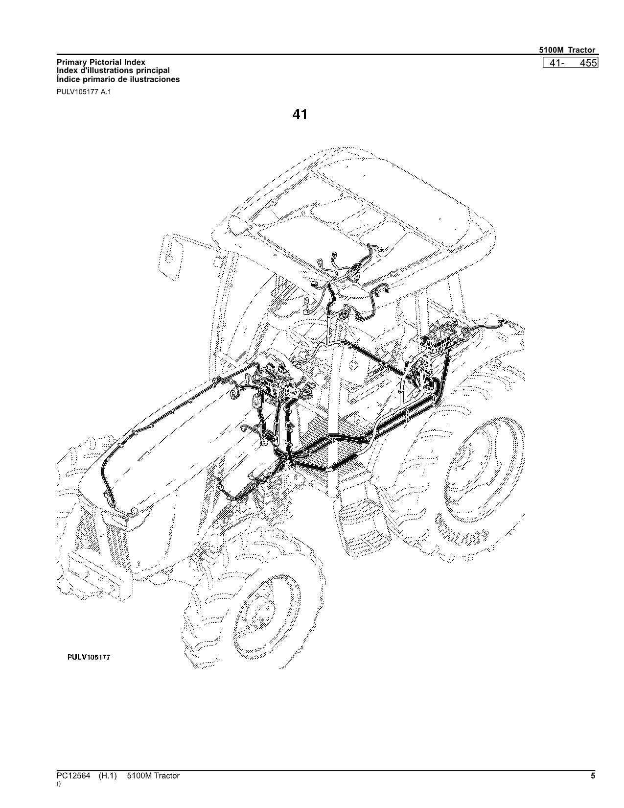
Understanding the arrangement and connections of various elements in mechanical equipment is essential for effective maintenance and repair. A clear visualization of how each unit integrates within the system can significantly simplify troubleshooting tasks and component replacements.
In this section, we focus on providing a detailed overview of structural placements and configurations that enhance the efficiency of your machinery. By examining each element’s specific role and positioning, you’ll gain valuable insights into optimizing the overall performance of your equipment.
Analyzing interconnected elements and their alignment not only aids in diagnostics but also plays a crucial role in preventing potential issues before they arise. With a solid grasp of these details, handling technical challenges becomes more straightforward, leading to prolonged machinery lifespan and reduced downtime.
Key Components of the John Deere 455
The design of this model is based on a blend of robust construction and efficient engineering. It features several essential elements that ensure optimal functionality, durability, and performance. Each component plays a vital role in the seamless operation of this machine.
- Engine System: The core of the equipment’s power, delivering consistent performance and reliability. It supports heavy-duty tasks and provides sufficient force to handle various operations efficiently.
- Transmission Mechanism: This element ensures smooth power transfer from the motor to the wheels, allowing for precise control and stability during movement across different terrains.
- Cooling Unit: A crucial part that prevents overheating by maintaining an ideal temperature, thereby extending the machine’s lifespan and maintaining its peak performance.
- Hydraulic Assembly: Responsible for powering attachments and additional equipment, it enhances versatility, making the unit adaptable for diverse applications in various conditions.
- Drive System: Provides the necessary traction and grip, ensuring effective navigation over challenging landscapes and contributing to the machine’s overall maneuverability.
The thoughtful integration of these components results in a machine capable of handling demanding tasks while maintaining efficiency and durability over extended periods of use.
Engine Assembly Breakdown
The comprehensive analysis of the engine’s structure focuses on understanding its individual components and how they function together. This section aims to simplify the intricate details of the mechanism, breaking down each part into its role within the larger system, ensuring a clearer perspective on the assembly as a whole.
Primary Components Overview
- Cylinder Block: Acts as the foundation, housing key elements crucial for the machine’s performance.
- Pistons: Move within the cylinders to generate power through controlled combustion.
- Crankshaft: Converts the pistons’ linear movement into rotational energy, driving the entire setup.
Supporting Mechanisms
- Valve System: Regulates the flow of air and fuel, ensuring the optimal mix reaches the combustion chamber.
- Timing Chain: Synchronizes the engine’s internal movements, keeping everything operating in precise harmony.
- Lubrication Circuit: Maintains smooth operation by reducing friction and cooling vital parts.
Transmission Components Overview
The transmission system is a critical assembly that ensures the effective transfer of power from the engine to the drive mechanism. It plays a fundamental role in optimizing speed, torque, and control, adapting to varying operational conditions. Understanding its structure and functionality is essential for maintaining peak performance and ensuring long-term reliability.
Core Elements of the System
The system comprises various interconnected elements that work in unison to achieve seamless operation. Key components include gear assemblies, shafts, and couplings that facilitate the precise modulation of force. Each part is designed to handle specific loads, ensuring smooth transitions between speed ranges and maintaining the overall efficiency of the machinery.
Role of Gear Sets and Shafts
Gear sets and shafts are fundamental to the mechanism, determining the conversion of engine power into mechanical motion. These elements are crafted to withstand substantial pressure while ensuring minimal energy loss during transmission. Proper alignment and engagement of these components are crucial to reduce wear and extend the operational lifespan of the system.
Hydraulic System Parts Layout
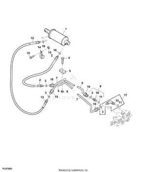
The hydraulic configuration within this equipment is a crucial aspect of its functionality. Understanding the arrangement and positioning of various components can significantly enhance maintenance and operational efficiency. This section provides an overview of how these elements interact to create a cohesive and effective system.
Core Components and Their Arrangement
The core components of the fluid-powered system include the pump, control valves, and actuators, each strategically placed to maximize performance. The pump serves as the heart of the system, generating the necessary force to move fluid through the network. Control valves regulate the flow, ensuring precise movement and operation, while actuators convert the fluid’s energy into mechanical power, enabling motion.
Interconnections and Flow Path
The seamless connection between the components is vital for maintaining a steady flow of hydraulic fluid. High-pressure lines transport the fluid from the pump to the actuators, while return lines guide it back for re-circulation. The overall layout is designed to minimize resistance and energy loss, enhancing the system’s efficiency. Regular inspections of these connections help in identifying potential issues early, ensuring uninterrupted operation.
Electrical Wiring Diagram Analysis
The study of an electrical schematic involves understanding the intricate connections and relationships among various components. It serves as a crucial guide in identifying how energy flows and how each element interacts within the system, highlighting potential areas for optimization or troubleshooting.
Key Components and Their Functions
Each unit within the electrical layout plays a distinct role, ensuring seamless operation of the entire assembly. Identifying these individual elements is essential for effective analysis and maintenance. Understanding the specific functions of these parts can assist in pinpointing issues quickly, reducing downtime, and enhancing system reliability.
Common Issues and Resolution Techniques
When analyzing the schematic, one might encounter frequent complications like poor connections or circuit disruptions. Addressing these problems often involves examining contact points, verifying signal continuity, and implementing corrective measures to restore functionality. By applying targeted solutions, it’s possible to enhance the system’s efficiency and prevent future malfunctions.
Fuel System Configuration
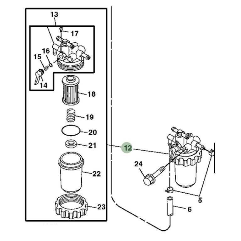
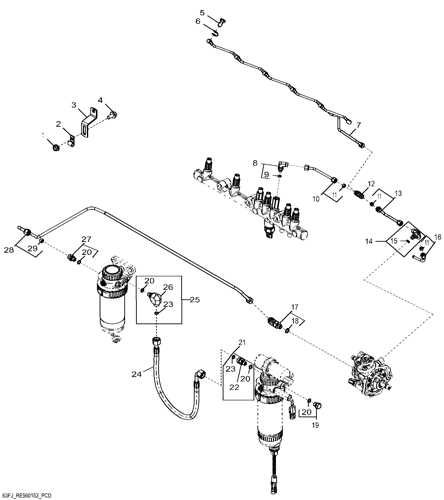
The arrangement of the fuel mechanism is crucial for ensuring optimal engine performance and efficiency. This section explores the various components and their roles in facilitating the smooth operation of the system.
Key elements involved in the configuration include:
- Fuel Tank: Serves as the primary reservoir for storing the fuel required by the engine.
- Fuel Pump: Responsible for transporting the fuel from the tank to the engine, maintaining the necessary pressure.
- Fuel Filter: Ensures that impurities and contaminants are removed before the fuel reaches the engine, promoting longevity and performance.
- Fuel Injectors: These components spray the fuel into the combustion chamber, allowing for efficient mixing with air and optimal combustion.
- Fuel Lines: The network of pipes that convey fuel from one component to another, designed to withstand varying pressures.
Understanding the layout and functionality of each component helps in diagnosing issues and performing maintenance effectively. Regular checks and adjustments can lead to improved performance and reduced operational costs.
Steering Mechanism Breakdown
The steering apparatus is a crucial element in ensuring precise control and maneuverability of a vehicle. This assembly consists of various components that work in tandem to facilitate smooth navigation and responsiveness when making directional changes.
Key Components
Essential elements of this mechanism include the steering wheel, column, and linkage system. The steering wheel allows the operator to input directional commands, which are transmitted through the column to the linkage, ultimately guiding the wheels as intended.
Functionality Overview
As the steering wheel is turned, the associated linkages adjust the angle of the wheels, ensuring that the vehicle follows the desired path. This system’s effectiveness hinges on the proper functioning of all its parts, as even minor malfunctions can lead to significant control issues.
Maintenance Considerations
Regular inspection and maintenance of the steering components are vital for optimal performance. This includes checking for wear and tear, ensuring all connections are secure, and addressing any play or looseness that may develop over time.
In summary, understanding the breakdown of the steering mechanism not only aids in effective operation but also in identifying potential issues early, ultimately contributing to the longevity and reliability of the vehicle.
Cooling System Structure
The cooling system is a vital component that ensures optimal temperature regulation within the machinery. Its primary function is to dissipate heat generated during operation, thereby preventing overheating and ensuring efficient performance.
This assembly typically consists of several essential elements, including the radiator, water pump, hoses, and thermostat. The radiator plays a crucial role in transferring heat from the coolant to the surrounding air. Meanwhile, the water pump circulates the coolant throughout the engine, maintaining a consistent flow to enhance heat exchange. Hoses facilitate the movement of coolant between different system components, ensuring that every part receives adequate cooling. Lastly, the thermostat regulates coolant flow based on temperature, preventing unnecessary cooling during startup and allowing the engine to reach optimal operating temperature quickly.
Understanding the configuration and function of each component is essential for effective maintenance and troubleshooting of the cooling system. Regular checks and timely replacements can prevent significant issues, enhancing the longevity and reliability of the equipment.
Drive Train Components Explanation
The drive train is a crucial system in any machinery, responsible for transmitting power from the engine to the wheels. Understanding its components is essential for optimizing performance and ensuring longevity. Each element plays a distinct role, contributing to the overall functionality and efficiency of the vehicle.
Key Elements of the Drive Train
Among the main components are the transmission, drive shafts, and differentials. The transmission adjusts the power output, allowing for varying speeds and torque. Drive shafts connect the transmission to the wheels, facilitating smooth movement. Differentials, on the other hand, enable wheels to rotate at different speeds, particularly during turns, enhancing traction and control.
Importance of Regular Maintenance
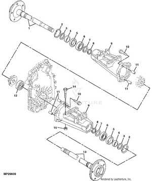
Regular inspection and maintenance of drive train components are vital for preventing wear and tear. Neglecting these parts can lead to significant performance issues and costly repairs. Ensuring that each element is functioning correctly not only improves efficiency but also extends the lifespan of the entire system.
Suspension Parts Arrangement
The configuration of suspension components plays a crucial role in ensuring optimal performance and comfort for the vehicle. Understanding how these elements work together is essential for maintaining stability and enhancing ride quality.
Key components within the suspension system include:
- Shock absorbers
- Struts
- Control arms
- Sway bars
- Spring assemblies
Each component contributes to the overall function of the suspension, providing support and damping for a smooth experience on various terrains.
To further comprehend the arrangement of these components, it is beneficial to consider the following:
- Shock Absorbers: These devices control the movement of the suspension, ensuring that the vehicle remains stable during travel.
- Control Arms: They connect the wheel assembly to the vehicle frame, allowing for up and down movement while maintaining alignment.
- Sway Bars: These components reduce body roll during turns, enhancing handling and stability.
- Spring Assemblies: They support the weight of the vehicle and absorb shocks from the road surface.
Understanding the layout and interaction of these components is vital for effective maintenance and repairs.
Maintenance Tips for John Deere 455
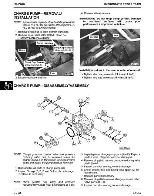
Proper upkeep is essential for ensuring the longevity and efficiency of any equipment. Regular maintenance not only enhances performance but also helps in identifying potential issues before they escalate. Following a systematic approach can lead to smoother operation and reduced repair costs.
1. Regular Inspections: Conduct frequent checks on various components to ensure everything is functioning as intended. Look for signs of wear, leaks, or damage that may require immediate attention.
2. Fluid Levels: Keep an eye on all fluid levels, including oil, coolant, and hydraulic fluids. Maintaining the correct levels is crucial for optimal performance and preventing overheating or mechanical failure.
3. Cleaning: Regularly clean the exterior and interior parts of the machinery. Dust and debris can hinder performance and lead to overheating. A clean machine is not only more efficient but also easier to maintain.
4. Follow the Manual: Always refer to the user manual for specific maintenance guidelines. The manufacturer provides essential information regarding service intervals, lubrication points, and other critical maintenance tasks.
5. Seasonal Checks: Perform seasonal maintenance to prepare for changing weather conditions. This may include checking belts, hoses, and tires, ensuring they are in good condition for optimal operation.
6. Professional Service: If unsure about performing maintenance tasks, consider consulting a professional. Regular servicing by trained technicians can help prevent major issues and extend the life of the equipment.