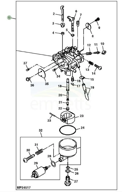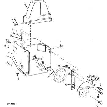
When it comes to maintaining a snow blower, knowing how each element functions is essential. Each piece has a specific role, contributing to the overall efficiency of the machine. Being familiar with these key elements can greatly enhance the performance and lifespan of your equipment.
Over time, it’s normal for certain parts to wear out and require replacement. Understanding how they fit together and operate within the system can simplify both maintenance and repair tasks. By gaining insight into the structure and functionality of the equipment, users can prevent major breakdowns and ensure smooth operation during the winter months.
Proper upkeep of the machine can significantly reduce the need for repairs. Recognizing common issues early and knowing which components to inspect can make a big difference in long-term
John Deere TRS24 Parts Overview

Understanding the structure and components of a snowblower is essential for maintaining its performance and ensuring long-lasting use. The system includes various mechanical and functional elements, each working together to deliver efficient results. Whether it’s clearing heavy snow or handling routine maintenance, recognizing key features is important for smooth operation.
Key Functional Components
The machine is equipped with several critical elements, including the engine, auger system, and drive mechanisms. These components are designed to withstand challenging weather conditions while providing optimal snow removal capabilities. Proper upkeep of these areas ensures consistent functionality during the winter season.
Maintenance and Care
Regular inspection and servicing are crucial to prolonging the life of the
Snowblower Engine Components Explained
The engine of a snowblower is the heart of the machine, responsible for powering various mechanisms that make snow removal possible. It is a complex system consisting of several key elements working together to ensure the device functions smoothly and efficiently. Understanding these components helps in maintaining the equipment and ensuring optimal performance during harsh winter conditions.
Engine Block and Cylinders
The engine block forms the core structure of the motor, housing essential elements like cylinders. These cylinders are where
Blades and Augers: Key Parts
The cutting and gathering components of snow removal equipment play a crucial role in ensuring effective performance. These elements are designed to handle varying conditions and ensure smooth operation during tough tasks. The right choice and maintenance of these elements can significantly enhance efficiency.
- Blades: These are responsible for cutting through compacted snow and ice. The sharp edges of the blades make it easier to slice through even the hardest layers, helping the machine work efficiently in demanding conditions.
- Augers: These spiral-shaped components assist in moving the collected material towards the discharge area. They play an essential role in gathering snow and directing it for further processing, ensuring continuous flow without clogging.
Understanding the Drive System
The drive system plays a crucial role in ensuring smooth and efficient movement. It transfers power from the engine to the wheels or tracks, allowing the machine to operate effectively across various terrains. A solid understanding of how this system functions is essential for maintaining performance and durability.
Main Components of the Drive System
The drive system is composed of several interconnected parts that work together to deliver power and control speed. Below is a breakdown of the key components:
| Component | Function | |||||||||||||||||||||||||||||||||||||||||||
|---|---|---|---|---|---|---|---|---|---|---|---|---|---|---|---|---|---|---|---|---|---|---|---|---|---|---|---|---|---|---|---|---|---|---|---|---|---|---|---|---|---|---|---|---|
| Transmission | Transfers power from the engine to the drivetrain, controlling speed and torque. | |||||||||||||||||||||||||||||||||||||||||||
| Component | Description |
|---|---|
| Battery | Stores electrical energy to start the engine and power electrical systems. |
| Alternator | Generates electrical power while the engine is running, recharging the battery. |
| Starter Motor | Initiates the engine’s operation by turning the flywheel. |
| Fuse Box | Protects electrical circuits by preventing overloads and short circuits. |
| Wiring Harness | Connects various electrical components, allowing for efficient communication and power distribution. |
Control Handles and Levers Guide

The operation of machinery relies significantly on the functionality of control handles and levers. These components play a crucial role in directing various actions and adjustments, enhancing the overall user experience. Understanding their design and layout is essential for efficient manipulation and maintenance of the equipment.
Types of Control Mechanisms
Control handles and levers come in various forms, each serving specific purposes. Some are designed for steering and navigation, while others allow for speed adjustments or implement activation. Familiarizing oneself with these different types helps in selecting the appropriate mechanism for a particular task.
Maintenance Tips
Regular inspection and maintenance of control handles and levers are vital to ensure optimal performance. It is recommended to check for any signs of wear or damage, lubricate moving parts, and ensure that all connections are secure. By adhering to these practices, users can prolong the lifespan of these essential components and maintain operational efficiency.
Troubleshooting Transmission Issues
Addressing complications within the transmission system can be a daunting task for many users. Recognizing the signs of malfunction is the first step in the diagnostic process. Common indicators such as unusual noises, fluid leaks, or erratic shifting behaviors can suggest underlying problems that require careful examination.
Identifying Common Symptoms
Users should pay attention to specific symptoms that may arise during operation. Unresponsive gears can indicate an issue with the hydraulic system or the shifting mechanism. Additionally, strange sounds during gear changes often point to wear and tear in internal components. It is crucial to address these symptoms promptly to prevent further damage.
Conducting Basic Checks
Before delving into more complex repairs, performing a few basic checks can help pinpoint the issue. Ensure that the fluid levels are adequate and that there are no visible leaks around the transmission area. Inspecting the filters for clogs can also improve overall functionality. By addressing these initial factors, users can often resolve minor issues before they escalate.
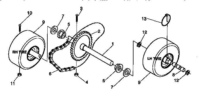
Wheels and Tracks Breakdown

This section delves into the essential components that contribute to the mobility of equipment designed for diverse terrains. Understanding the configuration and functionality of these elements is crucial for maintaining optimal performance.
| Component | Description | Functionality |
|---|---|---|
| Wheels | Round elements that provide surface contact and support. | Facilitate movement across solid ground while maintaining stability. |
| Tracks | Continuous bands that distribute weight over a larger area. | Enhance traction and reduce ground pressure, ideal for softer surfaces. |
| Track Rollers | Components that assist in guiding and supporting the tracks. | Help maintain alignment and smooth operation of the tracks. |
| Idler Wheels | Wheels that guide the track and maintain tension. | Prevent slack in the track system for improved performance. |
Replacement Parts for TRS24 Snowblower
When it comes to maintaining a reliable snow-clearing machine, knowing which components can be replaced is crucial for optimal performance. The availability of high-quality alternatives ensures that the equipment continues to function effectively, allowing users to tackle winter conditions without difficulty.
Essential Components
Understanding the key elements that may require replacement is vital for the longevity of the snow removal equipment. These parts are designed to handle the rigors of winter tasks, and selecting the right substitutes can significantly enhance efficiency.
Commonly Replaced Items
Below is a table outlining some frequently replaced items for snow-clearing devices:
| Component | Description | Function |
|---|---|---|
| Auger | Metal spiral blade used to collect and propel snow | Efficient snow intake and discharge |
| Shear Pins | Protective fasteners designed to break under excessive load | Prevents damage to the auger and drive system |
| Belt | Rubber component connecting the engine to the auger | Transmits power from the engine to the auger |
| Skid Shoes | Adjustable pads that control the height of the machine | Prevents scraping of the surface while clearing |
| Control Cable | Cable used to operate various functions | Enables user control over the equipment |
