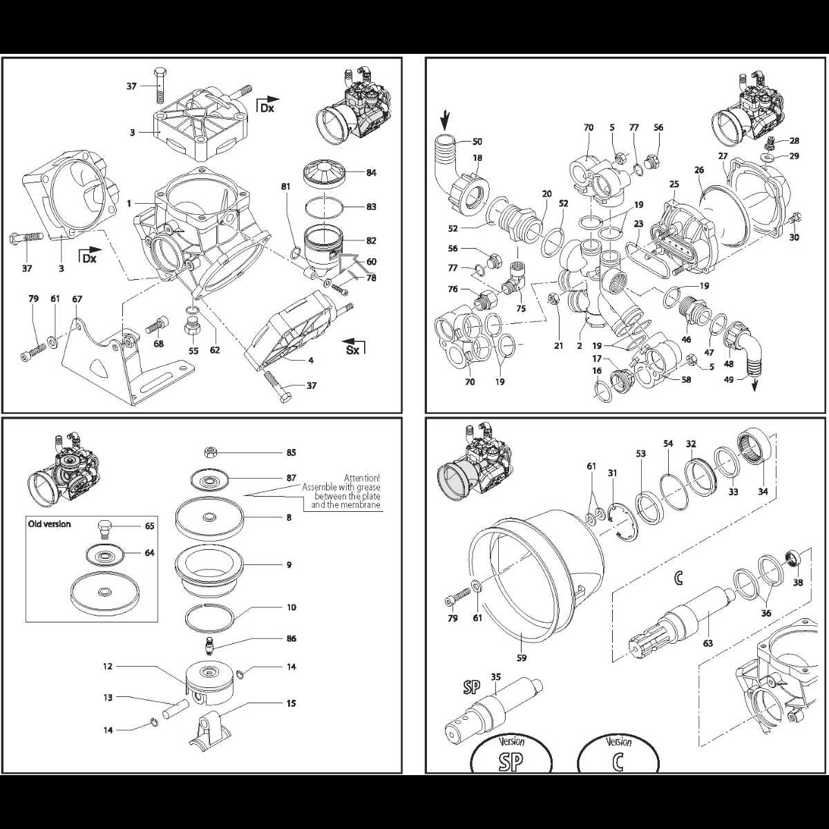
In the world of machinery, comprehending the arrangement of essential elements is crucial for effective maintenance and repair. This section aims to illuminate the intricate design of various components, providing a clearer view of their functionality and interconnectivity.
Detailed illustrations serve as valuable resources for technicians and enthusiasts alike, enabling them to navigate the complexities of mechanical assemblies. By grasping the layout, one can easily identify the roles of individual parts and their interactions within the system.
As we delve into this topic, we will explore the significance of clear representations that not only aid in troubleshooting but also enhance overall operational efficiency. A thorough understanding of how each segment fits into the larger mechanism is essential for achieving optimal performance.
Annovi Reverberi Parts Diagram
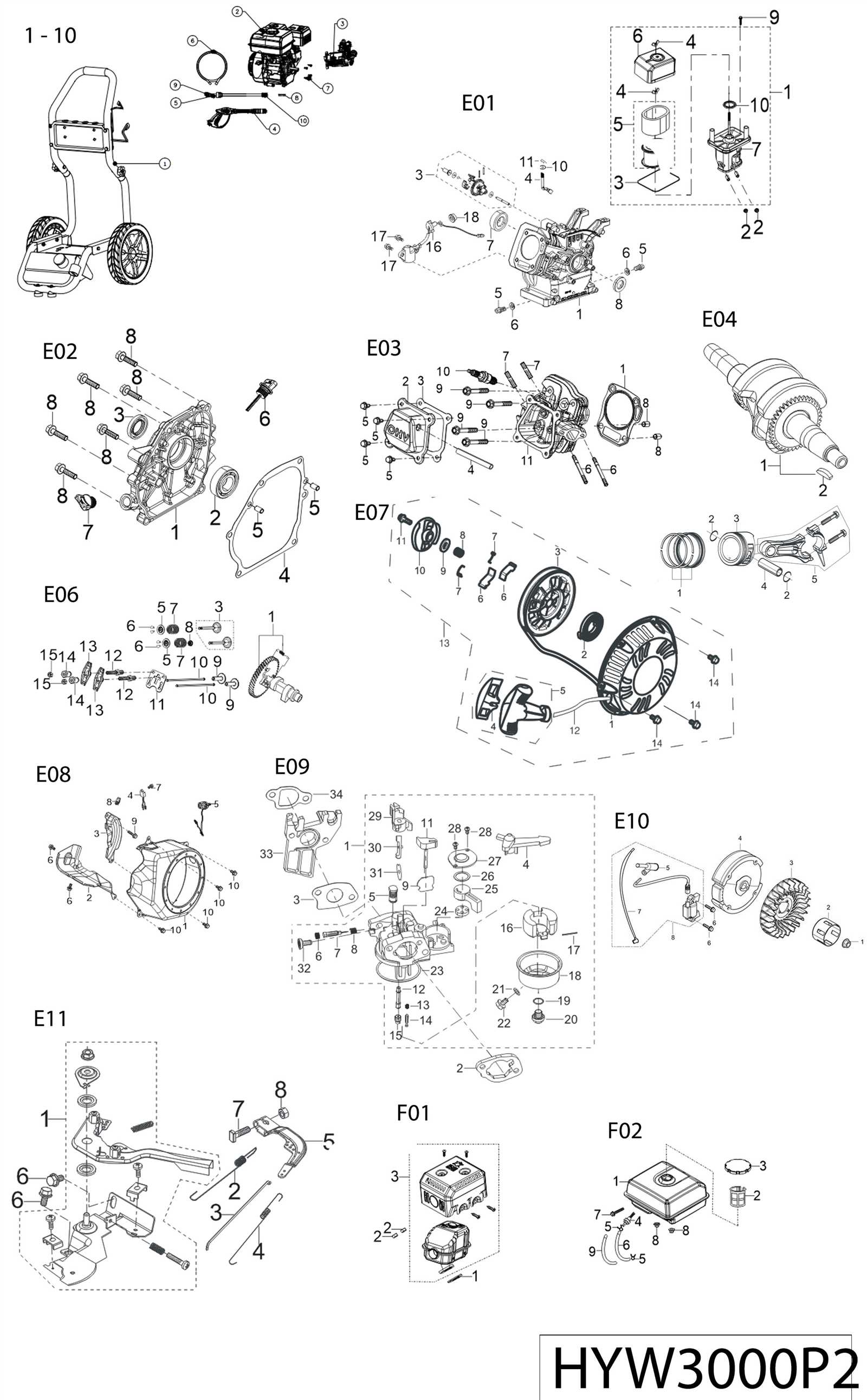
This section provides an overview of the essential components of a specific equipment model, showcasing how each element interconnects to ensure optimal functionality. Understanding these elements is crucial for effective maintenance and troubleshooting.
Key Components
- High-pressure pump
- Pressure relief valve
- Trigger gun assembly
- Hoses and fittings
- Motor or engine
Functionality Overview
Each component plays a vital role in the overall operation. The high-pressure pump generates the necessary force, while the trigger gun allows for controlled application. Proper maintenance of these elements enhances performance and extends the lifespan of the equipment.
Understanding the Components
In any mechanical system, each element plays a vital role in ensuring optimal performance. Recognizing how these individual pieces interact can significantly enhance your comprehension of the overall functionality. This section will explore the essential constituents that make up the assembly, providing insights into their purposes and contributions.
- Pump: The primary mechanism responsible for fluid movement, essential for operational efficiency.
- Motor: Supplies the necessary power to drive the pump, facilitating the entire process.
- Hoses: Connect various components, allowing for fluid transfer between sections.
- Valves: Control the flow of liquid, ensuring proper distribution and pressure management.
- Filters: Remove contaminants from the fluid, protecting the system’s integrity.
Each of these elements contributes uniquely to the system’s functionality. Understanding their roles will aid in troubleshooting and maintenance, leading to a more efficient operation.
Importance of Accurate Diagrams
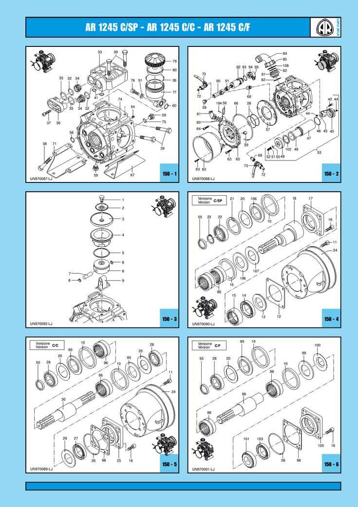
Clear representations of components and their relationships are crucial in any technical field. These visual aids serve as essential tools for understanding complex systems, enabling users to identify specific elements and their functions effectively.
Precision in these representations ensures that users can navigate assembly and maintenance tasks without confusion. Accurate visuals reduce the risk of errors, which can lead to operational failures or costly repairs.
Moreover, well-crafted illustrations facilitate effective communication among team members and enhance training processes. When individuals can rely on precise visual references, they are better equipped to perform their duties confidently and competently.
Common Issues with Parts Diagrams
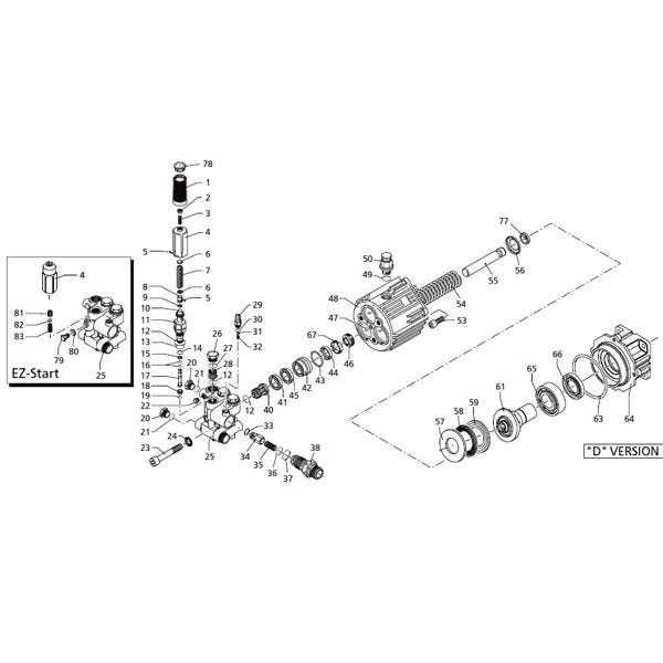
Understanding visual representations of components can often lead to confusion and frustration. Many users encounter difficulties due to unclear labeling, lack of detailed information, or discrepancies between the visuals and the actual items. These challenges can hinder effective identification and replacement of essential elements in machinery.
One prevalent issue is the absence of comprehensive legends or keys that explain symbols and colors used in these illustrations. This lack of clarity can result in misinterpretations, making it harder for individuals to find the right replacements. Additionally, outdated visuals may not reflect the most current models, leading to further complications during maintenance or repairs.
Another common problem arises from the variation in terminology. Different manufacturers may use distinct names for similar components, which can create misunderstandings. Users may struggle to match the parts they need with the ones shown in the visuals, complicating the procurement process.
Furthermore, the complexity of some representations can overwhelm users, especially those with limited technical knowledge. Overly intricate images may obscure important details, making it difficult to pinpoint specific components. Simplified and more user-friendly illustrations could greatly enhance accessibility and comprehension.
Tools for Diagram Interpretation
Understanding technical illustrations requires a set of specialized instruments that facilitate analysis and comprehension. These tools can significantly enhance one’s ability to decode intricate schematics, ensuring effective troubleshooting and maintenance.
Here are some essential instruments commonly used for interpreting such visuals:
| Tool | Description |
|---|---|
| Digital Caliper | Allows precise measurements of components, aiding in identifying dimensions within the visual representation. |
| Multimeter | Essential for testing electrical connections and verifying functionality depicted in the schematic. |
| Color-coded Markers | Useful for annotating different sections, making it easier to follow various pathways or connections. |
| Reference Manuals | Provide additional context and explanations that support the information presented in the visuals. |
Identifying Replacement Parts
When it comes to maintaining and repairing machinery, understanding how to locate suitable components is crucial for efficient operation. This process often involves recognizing the specific elements that require substitution and ensuring compatibility with existing units.
To successfully identify suitable replacements, consider the following steps:
- Check the model number and specifications of the equipment.
- Refer to the user manual for a detailed list of components.
- Consult with a trusted supplier or manufacturer for recommendations.
Additionally, it is beneficial to familiarize yourself with common characteristics of components:
- Dimensions and shape
- Material composition
- Functional specifications
By following these guidelines, you can ensure a smoother process in finding the right items needed for maintenance or repair tasks.
Maintenance Tips for Longevity
Ensuring the durability and efficiency of your equipment requires consistent care and attention. Regular maintenance not only enhances performance but also extends the lifespan of the machine, preventing costly repairs and replacements.
Start by routinely checking all components for wear and tear. Clean any debris or buildup that may affect functionality. Lubricate moving parts to minimize friction and prevent rust. It’s essential to follow the manufacturer’s guidelines regarding intervals for inspections and service.
Additionally, storing the equipment in a dry, protected environment can greatly reduce the risk of damage from moisture or environmental factors. Keeping the machine covered when not in use can further safeguard it from dust and contaminants.
Lastly, always use high-quality consumables and parts to ensure optimal performance. Investing in good materials will yield better results and promote longevity in the long run.
Assembly Instructions Overview
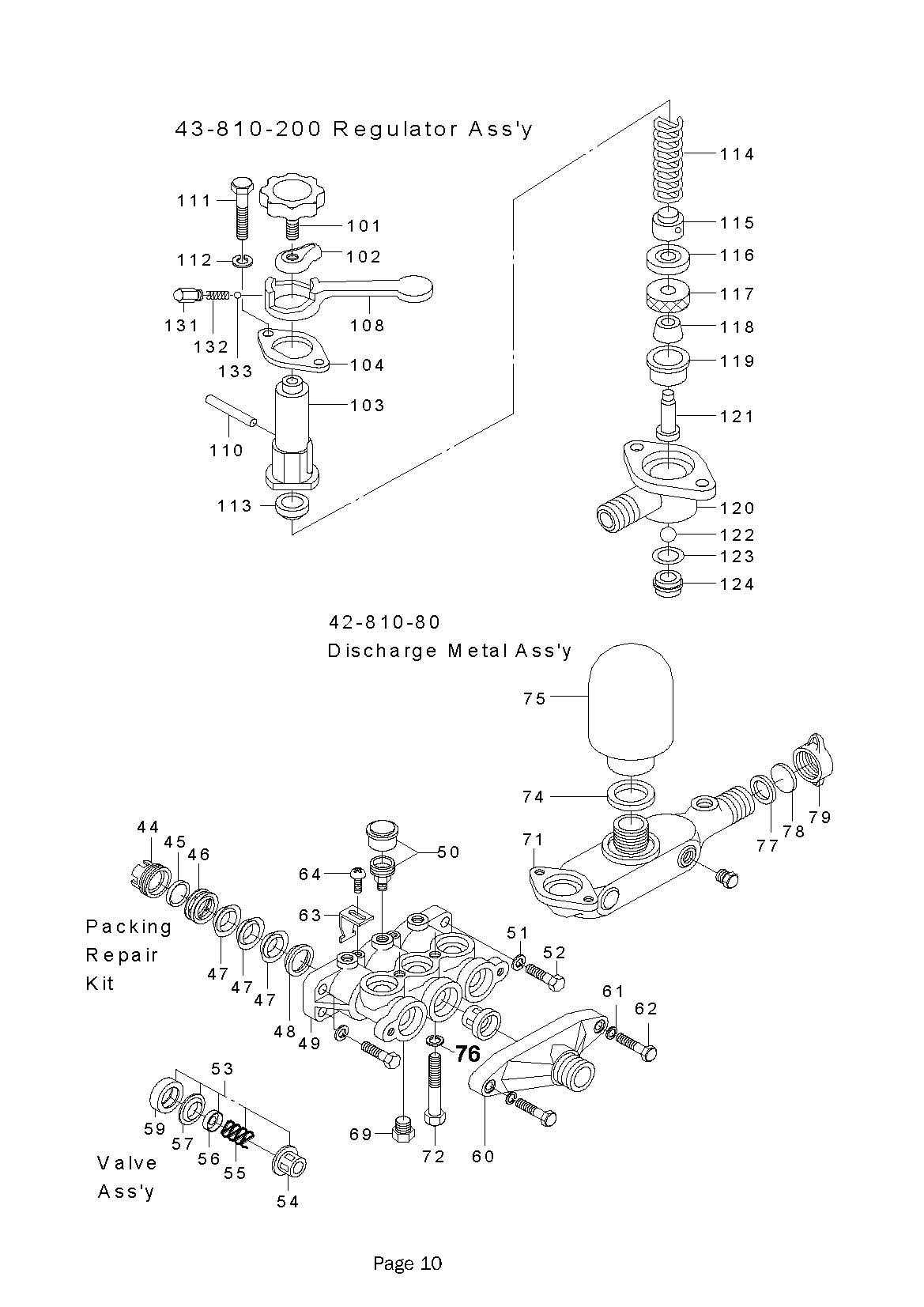
This section provides a concise guide on how to effectively combine various components to achieve optimal functionality. Following a systematic approach will ensure that each piece is correctly positioned, leading to a successful assembly process.
Step-by-Step Procedure
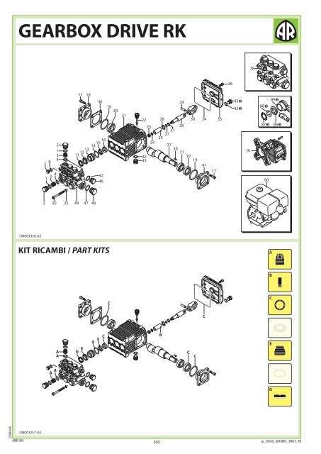
Begin by organizing all elements and ensuring that you have the necessary tools at hand. Follow these steps to ensure a smooth assembly:
| Step | Description |
|---|---|
| 1 | Gather all necessary components and tools. |
| 2 | Refer to the included guidelines for specific sequences. |
| 3 | Carefully connect the pieces, ensuring secure fits. |
| 4 | Perform a final inspection to verify that everything is in place. |
Tips for Successful Assembly
To enhance the assembly experience, consider the following recommendations: maintain a clean workspace, double-check each connection, and consult the manual if uncertainties arise. Proper handling and care during this process will lead to improved performance and longevity of the assembled unit.
How to Read Technical Drawings
Understanding technical illustrations is crucial for interpreting complex systems and components. These visual representations convey essential information about dimensions, relationships, and functionalities, allowing users to grasp intricate designs effectively.
Key Elements of Technical Illustrations
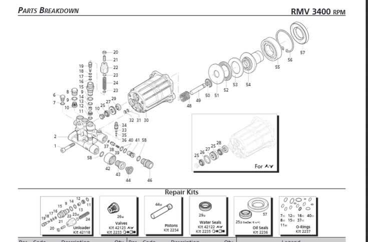
Familiarize yourself with the symbols, lines, and annotations used in these representations. Different line types indicate various features, while symbols provide insights into materials and assembly methods. Annotations often clarify specific measurements and instructions, making them vital for accurate comprehension.
Steps to Interpret Drawings
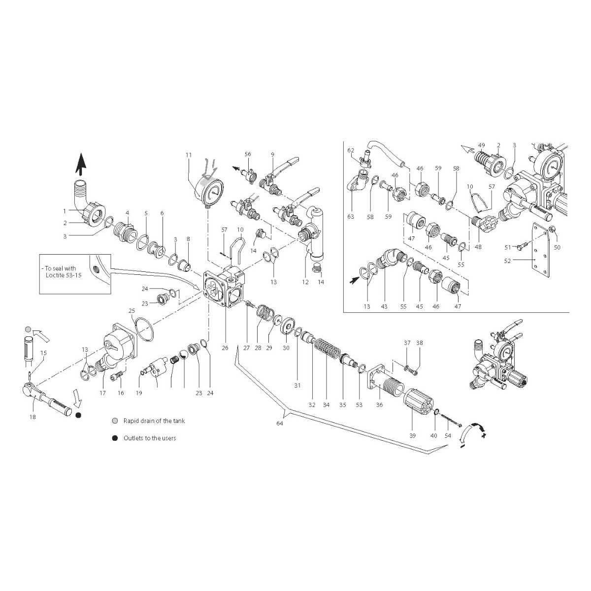
Begin by examining the title block, which typically includes essential details such as the drawing number and date. Next, identify the scale to understand the size of the components relative to one another. Analyze the views presented–top, side, and isometric–to form a complete picture of the assembly. Finally, refer to the legends and notes to gather additional context and instructions.
Comparing Different Models
When evaluating various units, it’s crucial to understand the distinctions and similarities that can impact performance and usability. Each model presents unique features that cater to different needs and preferences.
Key Features to Consider
- Durability: Assess the materials used and the expected lifespan.
- Efficiency: Look for specifications that indicate energy and water usage.
- Maintenance: Consider how easy it is to obtain replacement elements and service the unit.
Popular Models Overview
-
Model A:
Known for its high durability and efficiency, making it suitable for heavy-duty applications.
-
Model B:
This variant is compact and designed for residential use, prioritizing ease of maintenance.
-
Model C:
A versatile option that combines features from both previous models, appealing to a broader audience.
Common Misconceptions Explained
Many users encounter misunderstandings when dealing with maintenance components and their functionalities. These misconceptions can lead to ineffective repairs and unnecessary expenses. This section aims to clarify some prevalent beliefs to enhance user knowledge and confidence in handling such equipment.
- Misconception 1: All components are interchangeable.
- Misconception 2: Higher price guarantees better quality.
- Misconception 3: Installation is always straightforward.
- Misconception 4: Regular maintenance is optional.
This belief often leads to confusion. While some items may appear similar, they can differ significantly in performance and compatibility. Always refer to specific models before making a selection.
lessCopy code
Price does not always reflect the reliability or durability of an item. It is crucial to research and read reviews rather than solely relying on cost as an indicator of quality.
While many components are designed for easy installation, some require specific tools or expertise. Users should review guidelines carefully to avoid errors during setup.
Skipping routine checks can lead to severe issues down the line. Adhering to maintenance schedules is essential for ensuring optimal performance and extending the lifespan of the equipment.
Addressing these common misunderstandings helps users make informed decisions, ensuring better performance and reliability from their equipment.
Where to Find Official Resources
Accessing reliable information is essential for anyone seeking to understand the components and functionality of their equipment. Official documentation serves as a crucial tool, providing accurate details about various elements and how they work together. This section will guide you to the best places to locate these valuable resources.
Manufacturer Websites
The primary source for trustworthy information is the manufacturer’s official website. Here, you can find comprehensive manuals, technical guides, and specific product information that can aid in your understanding of the system. Look for sections dedicated to support or documentation, where resources are often categorized for easy navigation.
Authorized Distributors
Another excellent option is to explore the websites of authorized distributors. These platforms often feature sections for product documentation, including user manuals and troubleshooting guides. By visiting these sites, you can ensure you are accessing validated resources that align with your equipment.
Using Diagrams for Troubleshooting
Visual representations play a crucial role in identifying and resolving issues within complex systems. By providing a clear overview of components and their interconnections, these illustrations facilitate a more intuitive understanding of potential malfunctions and corrective actions.
When faced with a malfunction, it’s beneficial to refer to these visual guides, as they can help pinpoint the source of the problem. Here are some advantages of utilizing such illustrations during troubleshooting:
| Advantage | Description |
|---|---|
| Clarity | Visual aids simplify the identification of elements within a system. |
| Efficiency | Quickly locate potential failure points, saving time in diagnosis. |
| Guidance | Step-by-step instructions can be more easily followed with visual support. |
| Reduction of Errors | Minimize mistakes by providing a clear reference for assembly or disassembly. |
Incorporating visual tools into the troubleshooting process can enhance both accuracy and speed, making it an invaluable practice for effective maintenance and repair.