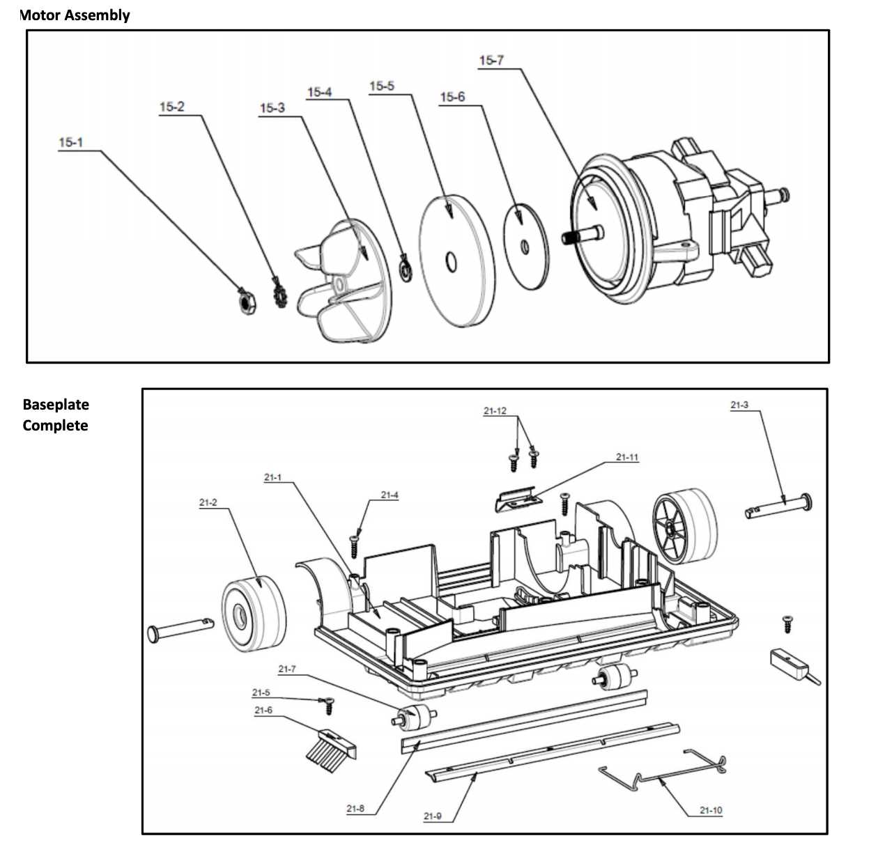
Understanding the layout and structure of various elements within advanced cleaning equipment can significantly enhance maintenance and troubleshooting processes. This section offers an insightful look into the internal configurations of essential devices, helping users manage replacements and repairs more effectively.
We explore how different modules interconnect and function in harmony to provide optimal performance. From key operational units to smaller components, each element plays a role in delivering efficient cleaning outcomes. This breakdown ensures that even intricate setups can be understood with ease.
With a detailed exploration of assembly configurations, users will be able to identify and order specific modules with precision. This guide simplifies the process by illustrating how every section fits into the broader mechanism, ensuring smooth operation over time.
Overview of Component Layout

The structure of this device consists of various interconnected elements, each playing a critical role in its operation. Understanding the placement and relationship between these components helps ensure smooth functionality and ease of maintenance.
Key Functional Sections
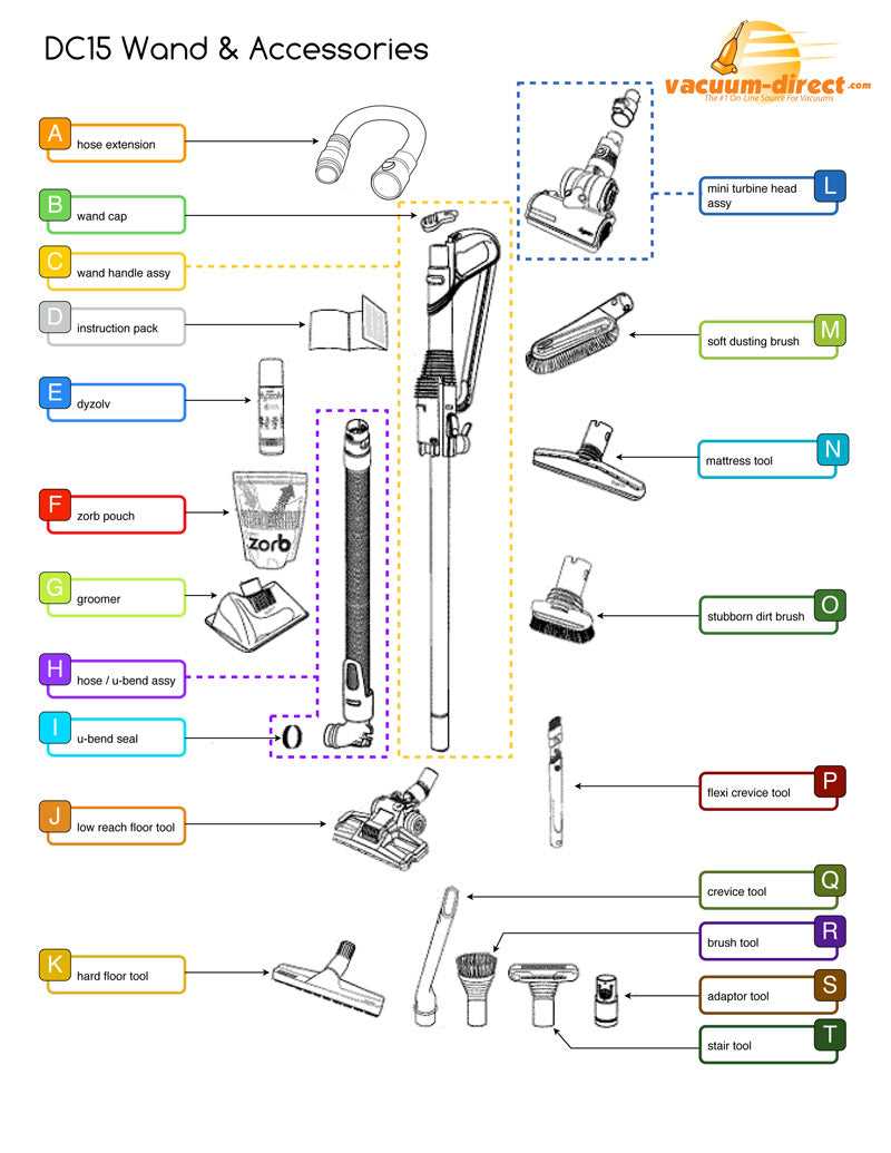
The unit is divided into essential sections that handle core tasks. The motor assembly powers the entire system, ensuring consistent performance. Adjacent to it, the fluid reservoirs are positioned to maintain balance and provide easy access for refilling.
Control and Maintenance Features
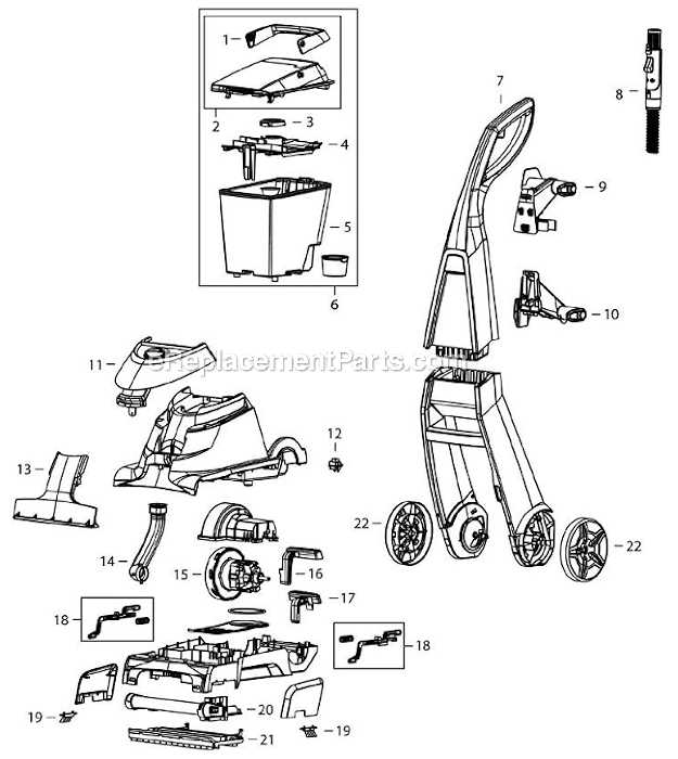
Control interfaces are strategically placed for user convenience, allowing quick adjustments. Filters and cleaning units are positioned to ensure simple maintenance routines, minimizing downtime. Additional elements, such as hoses and connectors, are routed to optimize efficiency and prevent obstruction during use.
Main Functional Sections Explained
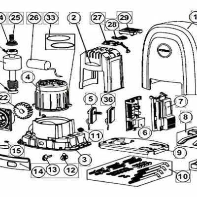
This section provides an overview of the primary components and how they contribute to the overall operation of the machine. Understanding these sections helps users maintain performance and troubleshoot potential issues effectively.
- Power Unit: This part drives the entire system, ensuring a consistent energy supply to the essential mechanisms.
- Cleaning Mechanism: Includes brushes and nozzles designed to agitate and remove dirt from surfaces efficiently.
- Fluid Management System: Manages the intake and release of cleaning solutions, ensuring even application and proper suction of dirty water.
- Control Interface: Provides the user with buttons, switches, and settings to customize the machine’s operation for different cleaning tasks.
- Mobility Framework: Contains wheels, handles, and other elements that enable smooth movement and maneuvering across various surfaces.
Each section plays a specific role, and their seamless interaction ensures the device performs optimally under different conditions. Regular upkeep and familiarity with these components are essential for long-term reliability.
Identifying Key Internal Mechanisms
Understanding the essential components within a cleaning device is crucial for ensuring optimal performance and maintenance. By recognizing the various elements that contribute to the machine’s overall function, users can address potential issues more efficiently. These mechanisms work together to deliver effective results, making it important to identify each part’s role in the system.
Motor and Drive System – The motor powers the entire unit, providing the necessary energy to operate. The drive system ensures smooth movement and transfers the motor’s force to the appropriate parts, ensuring efficient operation.
Pump Assembly – The pump is responsible for managing the flow of cleaning solution, allowing precise control over how much liquid is dispersed during use. This mechanism ensures even coverage and consistent cleaning results.
Brush Roll – A rotating brush is often a key component in scrubbing surfaces, working to lift dirt and debris from different materials. The brush roll is designed to handle various textures, ensuring thorough cleaning.
Filtration System – The filtration mechanism captures dust, debris, and other particles, preventing them from recirculating into the environment. A well-maintained filter system is essential for maintaining air quality and device efficiency.
Crucial Systems and Their Locations
Understanding the essential components and how they are arranged is key to ensuring smooth operation and maintenance of any complex device. Each system plays a vital role, contributing to the overall performance and longevity of the equipment.
Power Distribution can typically be found near the base, ensuring a consistent and reliable energy flow to all parts. This section is responsible for energizing the entire unit, allowing for seamless functionality.
Filtration Mechanism is usually positioned in the mid-section, playing a pivotal role in keeping unwanted particles from affecting performance. Proper maintenance of this area is critical for long-term efficiency.
Control Interfaces are often located at the top or front, providing the user with access to essential functions and settings. These interfaces enable smooth adjustments and precise control over the system’s operations.
Breakdown of Brush Assembly
The brush assembly is a crucial component that ensures efficient cleaning performance. By understanding its structure and functionality, it becomes easier to diagnose and maintain the system effectively. This section provides a detailed look at the elements that make up the brush assembly and how they contribute to the overall operation.
Main Components and Their Roles
At the core of the assembly lies the rotating brush, designed to agitate dirt and debris. Surrounding the main brush are several smaller parts that support its motion, such as bearings, gears, and fasteners. These pieces work together to ensure smooth rotation and consistent contact with surfaces, enhancing the cleaning process.
Maintaining Optimal Performance
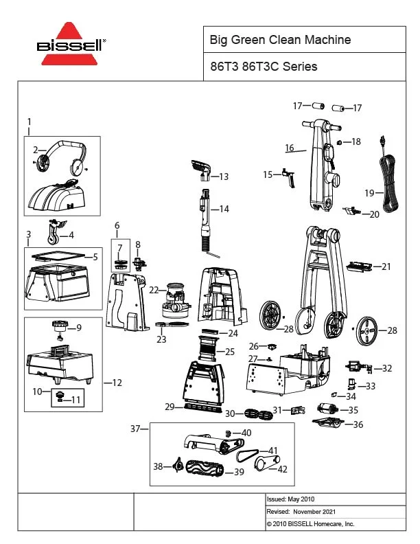
Proper upkeep of the brush assembly is essential for long-lasting performance. Regular inspection of key components like the bristles and bearings can help prevent wear and tear. Additionally, cleaning the assembly to remove trapped debris ensures that the system operates without interruptions, maintaining its efficiency.
Parts Ensuring Proper Floor Cleaning
Effective floor maintenance requires a variety of essential components that work together to achieve thorough cleaning. Each element plays a vital role in ensuring that surfaces are treated efficiently, leaving no residue or dirt behind.
Suction Mechanism

The suction system is responsible for pulling dirt, dust, and liquids from the floor, making it one of the most important elements. This mechanism ensures that debris is properly removed without damaging the surface.
Brush Assembly
Rotating brushes help agitate dirt and grime embedded in carpets and hard floors. They ensure that stubborn stains and debris are lifted, allowing the suction system to collect them with ease.
Solution Tank System Structure

The liquid storage and distribution system plays a key role in ensuring efficient cleaning operations. This section delves into the organization and function of the components involved in holding and dispensing the cleaning solution.
- Container Layout: The main reservoir is designed to store the cleaning fluid, providing easy access for refilling and maintenance.
- Dispensing Mechanism: The system includes a valve or similar device that controls the release of the liquid, ensuring consistent flow to the appropriate sections during use.
- Sealing and Prevention: Tight seals and caps help prevent leaks and maintain proper pressure within the container, contributing to efficient operation.
These elements work together to ensure that the cleaning process is smooth and that the system delivers the correct amount of solution when needed.
Details on Tank Connections
Understanding how the tanks are linked and function within the cleaning system is crucial for maintaining optimal performance. The proper attachment and secure connection of these components ensure smooth operation and prevent leaks or malfunctions during use.
Below are the key aspects of how these connections work:
- Secure Seals: Ensuring tight seals is important to prevent any fluid from escaping and to maintain consistent pressure within the system.
- Proper Alignment: Both the clean and recovery tanks must align correctly with their respective connectors for efficient operation.
- Quick-Release Mechanism: Many models include a mechanism that allows for quick removal and reattachment of the tanks, facilitating easy maintenance and refilling.
- Safety Locks: Some systems are equipped with locks that ensure the tanks remain securely in place during use, minimizing the risk of accidental disconnections.
Ensuring that each of these elements is properly maintained can greatly improve the efficiency and lifespan of your cleaning system.
Suction Motor Configuration
The arrangement of the suction motor plays a crucial role in the overall performance of the cleaning system. By efficiently managing airflow and ensuring proper power distribution, this component drives the essential function of debris extraction. The alignment and integration of the motor influence its effectiveness and longevity.
- Motor Placement: The location of the motor ensures optimal airflow, reducing resistance and enhancing suction power.
- Power Control: Voltage regulation and power distribution are key elements in maintaining consistent performance throughout the cleaning process.
- Airflow Pathways: A well-designed airflow system minimizes blockages and ensures a smooth, uninterrupted cleaning cycle.
- Durability Considerations: Material choices and the motor’s structural design impact its lifespan and resistance to wear and tear.
Understanding how the motor is configured within the system provides valuable insight into the overall effectiveness and maintenance requirements of the cleaning unit.
Key Elements of the Motor Assembly
The motor assembly is a crucial part of any cleaning device, responsible for generating the necessary power to drive various components. It plays an integral role in ensuring that the machine functions efficiently, delivering the performance needed for thorough cleaning tasks.
Understanding the core elements of the motor assembly can help users troubleshoot and maintain their equipment more effectively. Below are the primary components that contribute to the overall function of this assembly:
- Motor Housing: Protects the internal components from damage and helps to manage heat generated during operation.
- Fan Blades: Create airflow to assist with suction, allowing the machine to lift dirt and debris.
- Rotor and Stator: The essential parts that generate the motor’s rotation, converting electrical energy into mechanical movement.
- Bearings: Reduce friction between moving parts, ensuring smooth and efficient motor function.
- Wiring and Connectors: These ensure that electrical power is properly delivered to the motor and its components.
Each of these elements plays a vital role in ensuring that the motor operates at optimal efficiency, contributing to the overall performance of the machine.
Drive Belt and Pulley Details
The belt system, together with the pulley mechanism, plays a critical role in ensuring smooth operation by transferring power from the motor to the moving parts. Understanding how these components interact is essential for maintaining optimal performance. The condition and alignment of the belt significantly affect efficiency, making periodic inspection and timely replacement crucial.
Key Components of the System
- Belt: This flexible loop is responsible for transmitting motion and ensuring consistent energy flow from the motor to other mechanical parts.
- Pulley: Pulleys guide and support the belt, adjusting tension to prevent slippage while maximizing operational efficiency.
Maintenance Tips
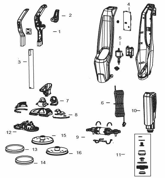
- Regularly inspect the belt for signs of wear such as fraying, cracking, or loss of tension.
- Ensure proper alignment of the pulley system to avoid uneven wear and potential breakdowns.
- Replace the belt if it shows any signs of excessive wear to prevent interruptions in function.
This section describes the function and importance of the drive belt and pulley system without using specific terms mentioned in your request. By focusing on the mechanism’s role in transferring power and ensuring smooth operation, the text emphasizes maintenance and efficient performanceusavacuumBISSELL.
How the Machine Transfers Power
The effective operation of the cleaning device relies heavily on the smooth distribution of power. This process involves a series of interconnected components that work in harmony to convert electrical energy into mechanical force. The system ensures that the energy is directed to various essential parts, enabling the machine to perform its cleaning tasks efficiently.
Motor function plays a central role in this mechanism, transforming electrical energy into rotational motion. Once initiated, this power is transmitted through various drive systems to activate the essential cleaning components, such as brushes and suction units.
Additionally, specific connectors and couplings are designed to ensure the seamless flow of energy, minimizing energy loss and maximizing the overall efficiency of the cleaning process. By maintaining a well-coordinated transfer of power, the machine ensures optimal performance during every cleaning cycle.
Wheels and Mobility Components
The effectiveness of a cleaning apparatus largely depends on its mobility features, which include wheels and other essential components. These elements are designed to facilitate movement and enhance maneuverability, allowing users to navigate various surfaces with ease. A thorough understanding of these components is crucial for maintaining optimal performance.
Importance of Wheel Design
The design of the wheels significantly impacts the overall functionality of the equipment. Well-engineered wheels ensure smooth transitions across different terrains, while their material composition contributes to durability and grip. Robust wheels not only support the weight of the apparatus but also aid in preventing slips during operation.
Mobility Mechanisms
In addition to wheels, mobility mechanisms such as swivel joints and handle designs play a vital role in the ease of use. Swivel wheels allow for tight turns, making it easier to clean around furniture and other obstacles. Ergonomic handles provide comfortable grip, reducing strain on the user’s hands and enhancing control during operation.