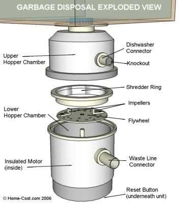
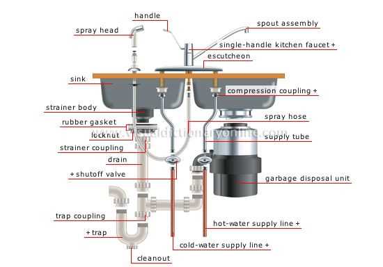
Understanding the structure of modern kitchen units that handle organic remains can be essential for maintenance and repairs. These appliances are designed with a variety of elements that work in unison to ensure efficient processing of food remnants, minimizing waste buildup in household environments.
Each component plays a crucial role in the unit’s operation, from the mechanisms responsible for breaking down substances to the connectors that link various parts. Gaining insights into the specific functions of these elements can help with troubleshooting and prolong the appliance’s lifespan.
By familiarizing yourself with the arrangement of these internal systems, you can better manage upkeep and identify potential issues before they lead to significant problems. This knowledge not only supports routine care but also empowers you to address minor malfunctions independently.
Identifying the Mounting Assembly
Understanding the core elements of the attachment setup is crucial for ensuring a secure and efficient installation process. This section will outline the key components involved in the assembly, guiding you through their identification and function.
- Support Ring: This element acts as the main structure, holding everything in place. It provides stability and ensures that the setup remains securely fastened.
- Mounting Flange: The flange serves as the connecting point between the unit and the sink base. Its design allows for a tight seal, preventing any unwanted movements or leaks.
- Cushion Gasket: Positioned between the main components, the gasket reduces vibrations and enhances the noise reduction during operation. Its placement is critical for smooth functioning.
- Locking Mechanism: This part is responsible for securing the entire arrangement. It often involves a twist or snap-lock design, making it easy to attach or detach the setup when needed.
Each element in the mounting assembly has a specific role, and recognizing their features will simplify the installation and maintenance process.
Exploring the Drainage Mechanism
The drainage system is a critical aspect of efficient waste management in kitchen fixtures. It ensures that liquids and small particles are guided smoothly through the pipeline, minimizing the risk of blockages or water buildup. Understanding how this mechanism functions can help in maintaining an uninterrupted flow and prevent common plumbing issues.
Key Components of the Flow System
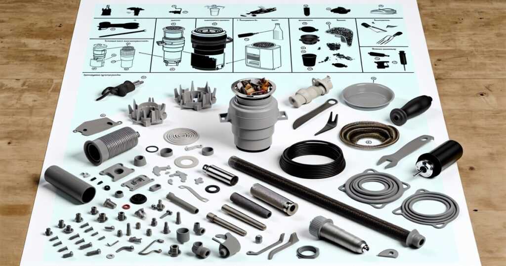
The drainage setup includes several interconnected elements that work together to channel the outflow effectively. Pipes of various sizes and shapes form the main route, while connectors ensure a tight seal between each section, reducing the possibility of leaks.
Maintaining Proper Flow
Proper upkeep of this system is essential to avoid clogs and ensure consistent operation. Regular inspection of the seals and junctions can help identify potential issues early, allowing for timely interventions to sustain optimal performance.
How the Disposal Grinder Operates
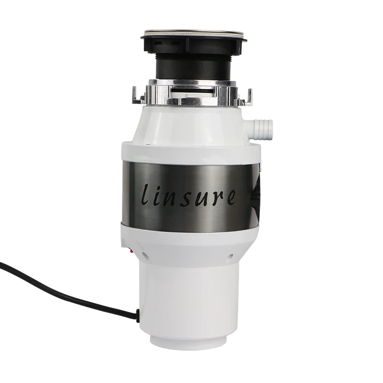
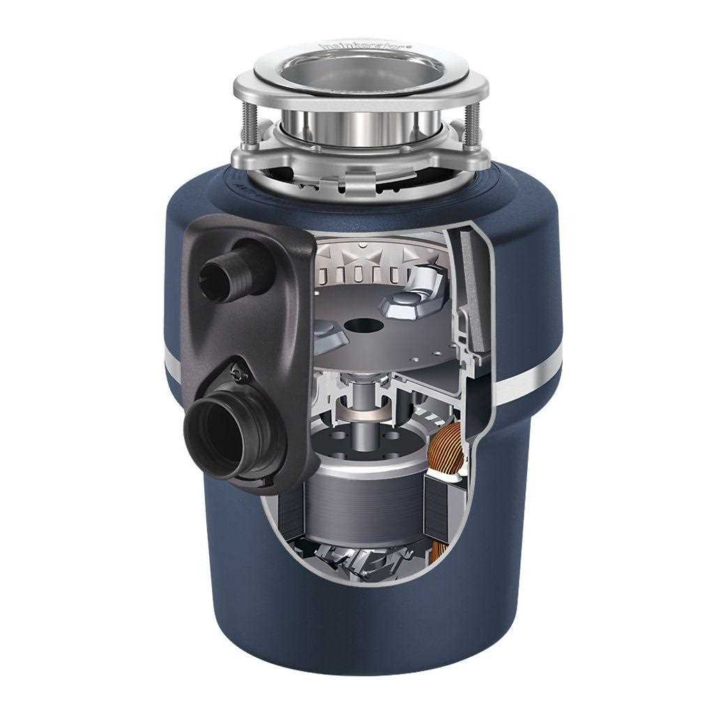
The internal mechanism is designed to efficiently break down waste into smaller pieces, allowing it to be easily flushed away. This process involves a rotating element that works in combination with other components to achieve a smooth reduction of materials.
The operation begins when the motor activates, causing the grinder to spin at high speed. This movement creates the necessary force to crush and shred the materials, turning them into finer particles. The design ensures that even tougher items can be broken down without causing a blockage.
Additionally, the system incorporates safety features that help prevent overloads or jams during operation. These mechanisms ensure a reliable and consistent performance, extending the lifespan of the unit and reducing maintenance requirements.
Understanding the Motor Unit Structure
The motor unit plays a crucial role in the functionality of the entire system. Its construction is designed to efficiently convert electrical energy into mechanical movement, driving the internal components with precision. A clear understanding of its layout can help in identifying any potential issues that might arise during operation.
Core Components and Their Roles
At the heart of the unit, the rotor and stator work in unison to generate rotational force. The rotor, typically located at the center, spins when energized, while the stator remains stationary, providing the magnetic field necessary for movement. Together, they create the mechanical force that powers the system’s operations.
Power Transmission Mechanisms
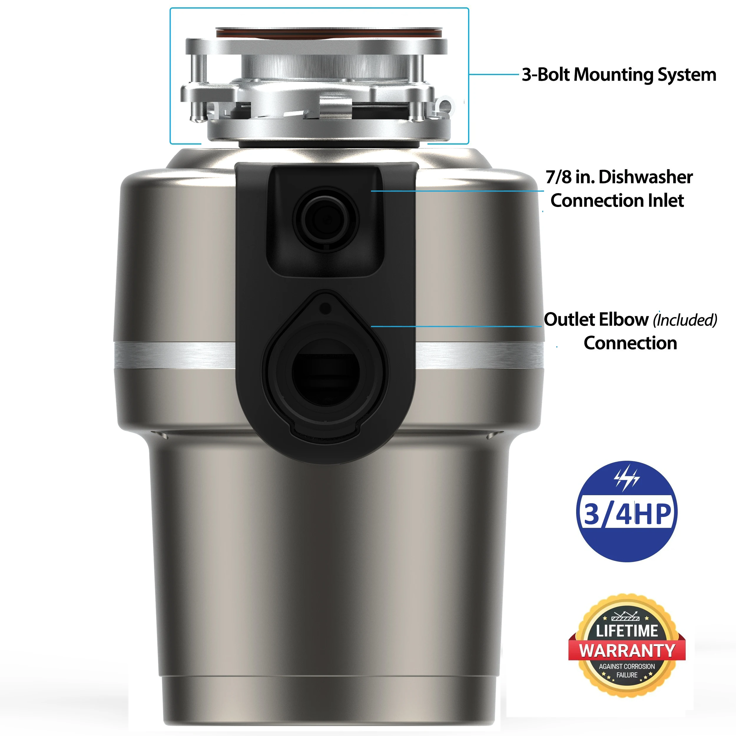
Energy generated within the motor is transferred through a series of gears and shafts, ensuring that the movement reaches the targeted sections with minimal energy loss. These mechanisms are precisely engineered to handle the load, maintaining efficiency and stability during the process.
Analyzing the Flywheel System
The flywheel mechanism plays a crucial role in the operation of this equipment, enhancing its efficiency and performance. It serves as a core component that directly influences how the entire setup functions, regulating movement and stability throughout the process.
Understanding the behavior of this system is essential, as it governs the rotational force and momentum distribution. The balance and precision of the flywheel determine the smooth execution of mechanical actions, minimizing potential disruptions during operation.
Inspecting the flywheel regularly can prevent issues related to imbalance or wear, ensuring the mechanism maintains its optimal condition. Its role in energy storage and release is vital, impacting the overall reliability and durability of the device’s functionality.
Examining the Impeller Plate Design
The impeller plate plays a crucial role in the efficient operation of waste processing systems. Its design significantly influences the performance, durability, and effectiveness of the unit, impacting how waste is managed and processed. Understanding the intricacies of this component can help users appreciate its importance in the overall system functionality.
Key Features of the Impeller Plate
- Shape and Size: The geometry of the plate is optimized to maximize the flow of materials.
- Material: Typically constructed from robust materials to withstand wear and tear during operation.
- Surface Texture: Often features a textured surface to enhance material movement and prevent clogging.
Maintenance Considerations
Regular inspection and maintenance of the impeller plate are essential for ensuring optimal performance. Key aspects to focus on include:
- Checking for wear and damage to identify the need for replacement.
- Cleaning the surface to prevent buildup that can hinder efficiency.
- Monitoring for any unusual noises during operation, which may indicate issues.
Role of the Splash Guard
The splash guard serves a vital function in kitchen appliances, designed to enhance safety and efficiency during operation. By preventing unwanted splashes and debris from escaping, it contributes to a cleaner environment and minimizes the risk of accidents.
Enhancing Safety
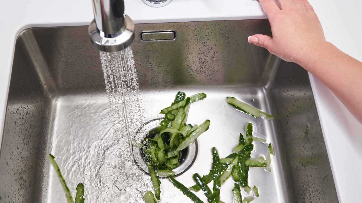
This component acts as a barrier that limits the projection of food particles and liquids, reducing the likelihood of slips and spills. Its presence not only protects users but also helps maintain the cleanliness of the surrounding area.
Improving Functionality
In addition to safety, the splash guard aids in optimizing the performance of the appliance. By containing the contents during use, it ensures that the device operates more effectively, promoting better results and longevity of the machine.
Connection Points and Electrical Wiring
This section provides a comprehensive overview of the key elements involved in establishing electrical connections for a specific system. Understanding these components is crucial for ensuring optimal functionality and safety during operation.
Essential Connection Points
Various connection points are utilized to facilitate the electrical integration of the system. Here are some of the most critical components:
- Power Supply Input: The entry point for electrical energy.
- Control Switch: Mechanism for initiating and terminating the electrical flow.
- Motor Connections: Links to the operational motors, essential for movement.
- Sensors: Devices that monitor performance and provide feedback.
Wiring Considerations
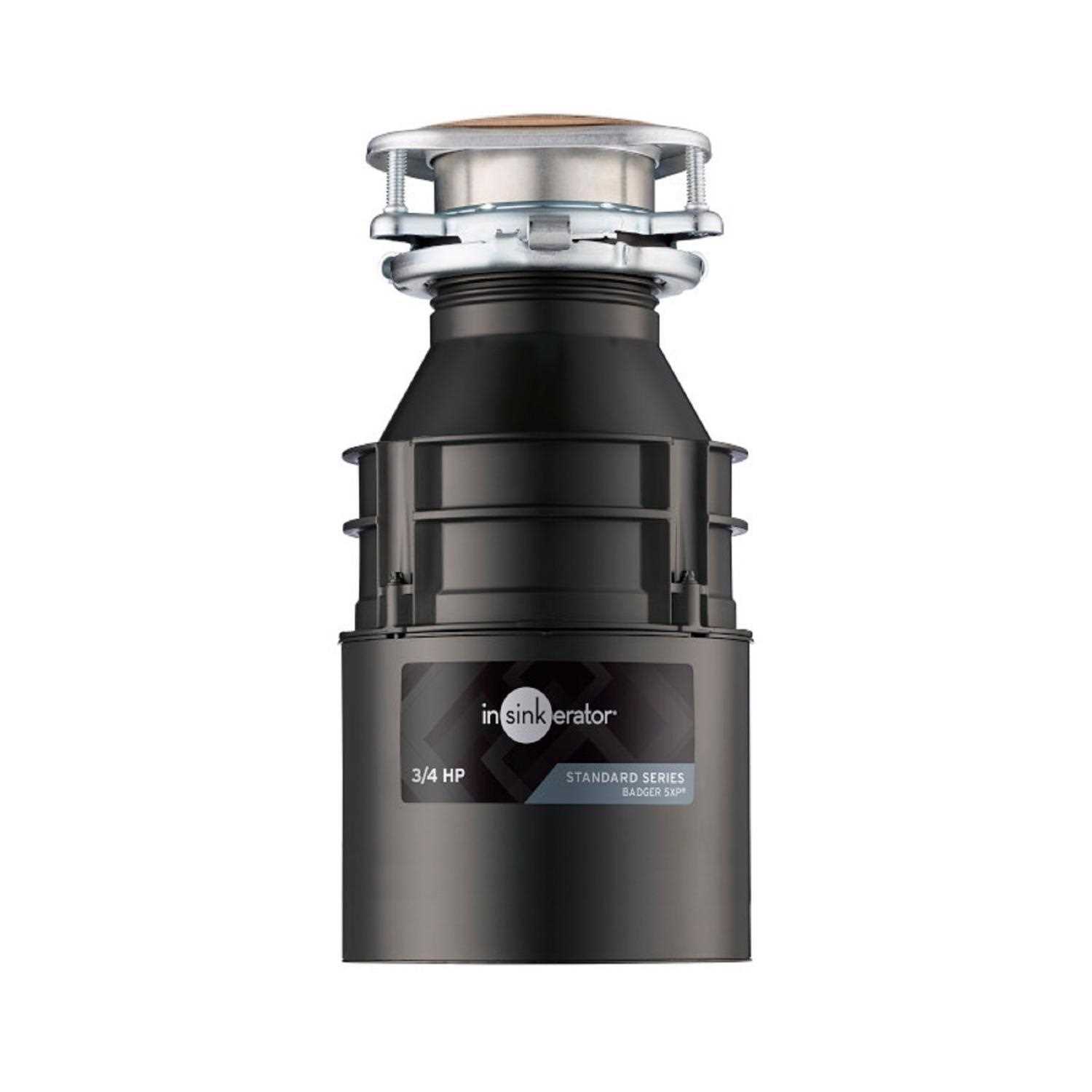
Proper wiring is essential for maintaining safety and efficiency. The following aspects should be considered:
- Use the correct gauge wire to handle the expected current load.
- Ensure all connections are secure to prevent shorts or disconnections.
- Follow electrical codes and guidelines for installation to maintain safety standards.
- Label wires clearly to avoid confusion during maintenance or repairs.
Placement of the Reset Button
The reset mechanism is a crucial feature in many waste management systems, designed to provide users with an easy way to restore functionality after a malfunction. Understanding the optimal location of this control can enhance user experience and ensure quick access in times of need.
Typically, the positioning of the reset switch is strategically determined to facilitate immediate access while minimizing the risk of accidental activation. The following table outlines common locations for the reset button in various models:
| Model | Reset Button Location |
|---|---|
| Model A | On the side panel, near the base |
| Model B | At the front, below the control panel |
| Model C | On the back, accessible through a small cover |
| Model D | Integrated into the top, surrounded by protective housing |
In conclusion, proper placement of the reset feature is essential for user convenience and effective operation. Familiarity with its location can significantly enhance troubleshooting efforts and restore functionality efficiently.
Maintenance Tips for Blades and Bearings
Regular upkeep of cutting elements and rotational components is essential for optimal functionality and longevity. By ensuring these parts are well-maintained, users can enhance performance, reduce wear, and prevent costly repairs. This section provides practical advice on how to care for these critical elements effectively.
Routine Inspection
Frequent examinations of cutting edges and bearings help identify wear and tear early. Look for signs of dullness in blades or unusual noises from bearings, which may indicate the need for adjustment or replacement.
Cleaning Techniques
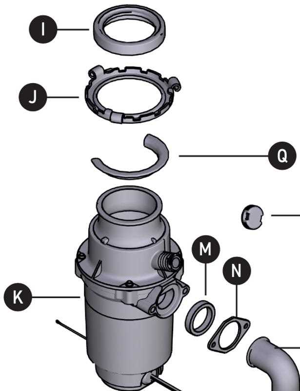
Keeping these components clean is vital for efficient operation. Accumulation of debris can hinder performance, so regularly remove any buildup using a damp cloth or a soft brush. Ensure that blades are free from rust and corrosion by applying suitable protective agents.
| Maintenance Activity | Frequency | Tools Needed |
|---|---|---|
| Inspect blades for dullness | Monthly | Visual check |
| Lubricate bearings | Every 3 months | Lubricant, cloth |
| Clean cutting edges | Weekly | Cloth, brush |
| Check for rust and corrosion | Monthly | Protective agent, cloth |
Inspecting the Waste Outlet Pipe
Examining the channel through which excess material exits is essential for ensuring optimal performance of your system. Proper maintenance of this component can prevent blockages and enhance the overall efficiency of the apparatus.
Signs of Potential Issues
Awareness of indicators that may suggest complications is crucial. Look out for the following:
- Unusual noises during operation.
- Slow drainage or backup in the system.
- Leaking around the connections.
- Unpleasant odors emanating from the outlet.
Steps for Effective Inspection
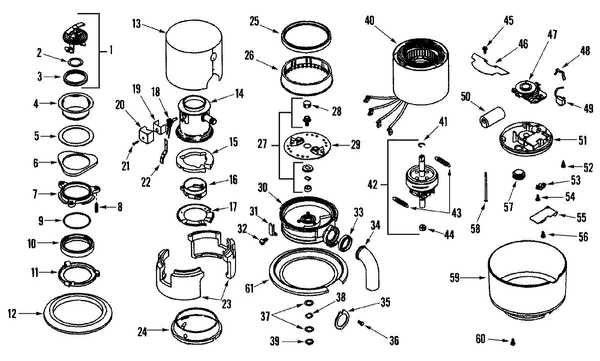
Conducting a thorough evaluation involves several key steps:
- Turn off the system and unplug it for safety.
- Carefully remove any coverings or shields to access the pipe.
- Check for visible damage or corrosion along the pipe.
- Inspect the joints and seals for any signs of leakage.
- Use a flashlight to examine the interior for clogs or obstructions.
- Reassemble all parts securely after inspection.