Blades designed
Wheels and Drive Assembly Breakdown
The wheels and drive mechanism are crucial components responsible for the movement and smooth operation of the machine. Understanding the structure and arrangement of these elements helps in maintaining their optimal performance, ensuring efficient mobility and power transmission. Each section of the system is designed to work in unison, providing both stability and control during operation.
The driving mechanism connects the motor to the wheels, transferring energy and enabling forward motion. This connection involves a series of gears, belts, and axles, which work together to ensure that the machine moves effortlessly across various surfaces. Regular inspection and maintenance of these components will ensure consistent functionality and longevity.
The wheels, in turn, are designed to handle different terrains, offering grip and support. They are mounted onto the drive system, allowing for seamless movement. The overall balance and
Handle and Control System Parts
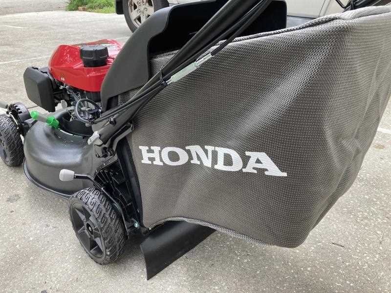
The handle and control system is essential for the effective operation of any machinery, enabling users to manage and direct functions with precision. This section highlights the various components that contribute to a seamless user experience.
- Grip Handle: This element provides a comfortable hold, allowing the operator to maintain control while maneuvering the device.
- Throttle Control: This component regulates the power output, enabling smooth acceleration and deceleration during operation.
- Brake Lever: An important feature that allows the user to stop or slow down the machinery efficiently, ensuring safety during use.
- Switch Panel: Houses various controls and indicators, providing quick access to operational functions and settings.
- Linkage Mechanism: Connects the handle to other functional elements, translating user inputs into actionable commands.
Understanding these elements is crucial for effective maintenance and optimal performance of the equipment. Regular checks and replacements can enhance the overall reliability and efficiency.
Air Filter and Exhaust Configuration
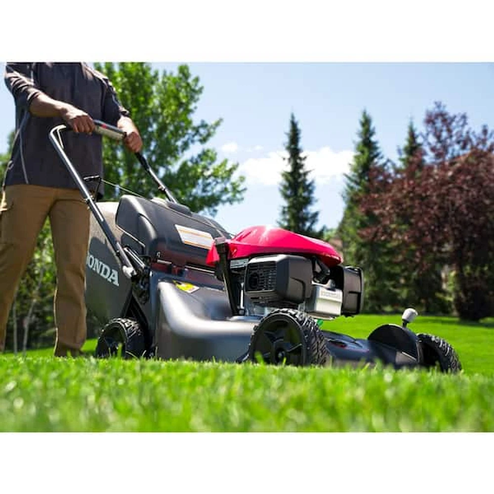
The efficiency of a machine’s performance is heavily influenced by its air intake and exhaust systems. These components play a crucial role in ensuring that the engine operates optimally by facilitating proper airflow, which is essential for combustion processes. A well-designed setup not only enhances power output but also minimizes emissions, contributing to a more environmentally friendly operation.
When considering the air filter, it is important to understand its role in filtering out contaminants that can affect engine performance. Regular maintenance and timely replacement of the filter can prevent potential damage and ensure smooth functioning.
| Component |
Description |
Function |
| Air Filter |
A device that removes particles from the air entering the engine. |
Enhances engine performance by ensuring clean air intake. |
| Intake Manifold |
A system that distributes the air-fuel mixture to the engine cylinders. |
Ensures optimal air distribution for effective combustion. |
| Exhaust Muffler |
A component designed to reduce noise from the exhaust system. |
Minimizes sound pollution while allowing exhaust gases to exit efficiently. |
| Exhaust Pipe |
A passage that directs exhaust gases away from the engine. |
Facilitates the exit of exhaust gases, improving engine efficiency. |
Transmission and Clutch Mechanism Details
The transmission and clutch system is a vital component in any machinery, playing a crucial role in the efficient transfer of power from the engine to the wheels. This system ensures that the vehicle operates smoothly and effectively, providing the necessary torque and speed variations for various driving conditions. Understanding the intricacies of these mechanisms can enhance maintenance practices and improve overall performance.
Transmission Overview
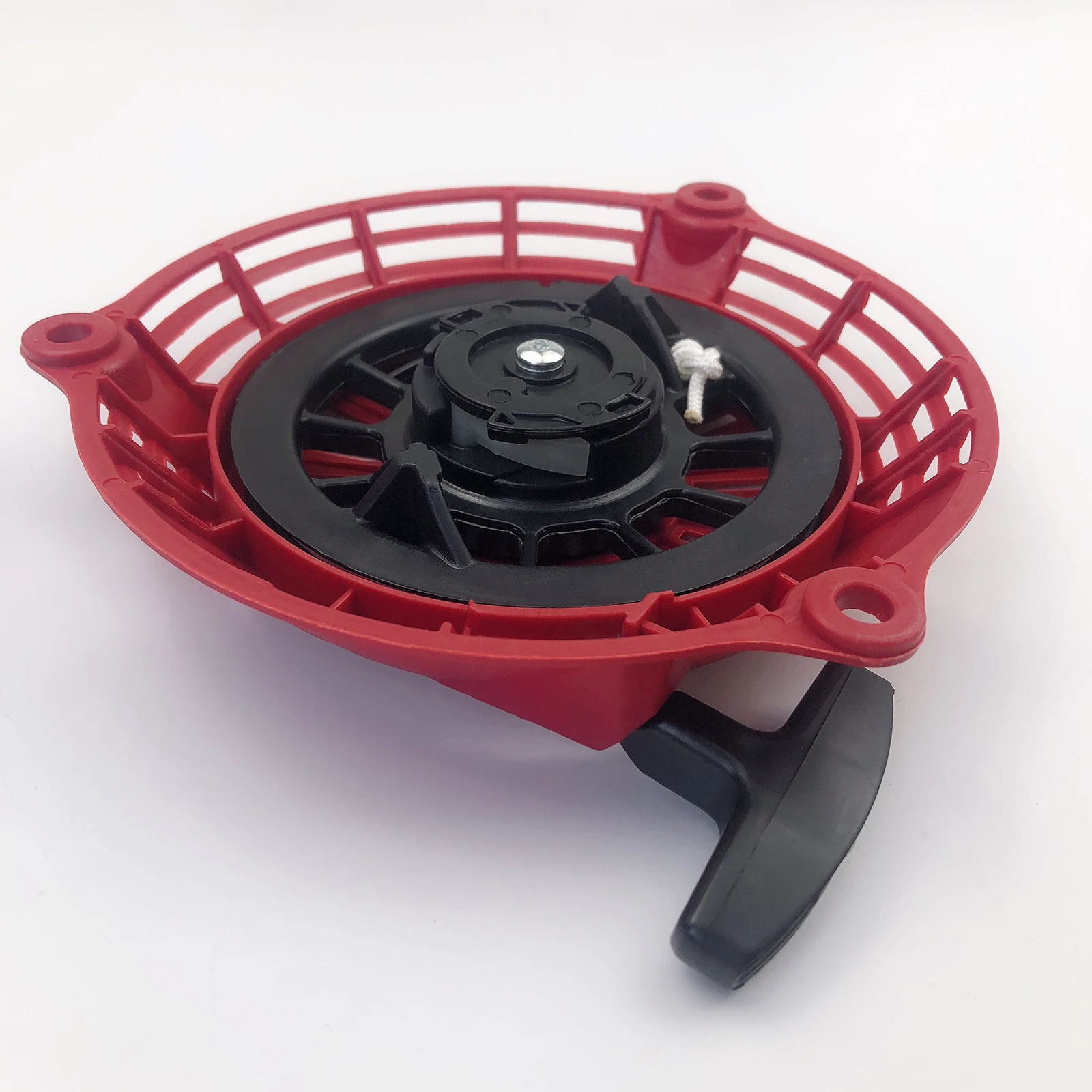
The transmission consists of several interconnected elements that work together to adjust gear ratios and facilitate the desired speed and torque output. Key components include the gearbox, gear shafts, and synchronizers, all of which contribute to the seamless shifting experience. Proper functioning of these parts is essential to ensure that the vehicle responds appropriately to driver inputs.
Clutch Functionality

The clutch serves as a bridge between the engine and transmission, allowing for smooth engagement and disengagement of power. This mechanism typically includes a pressure plate, clutch disc, and release bearing. By controlling the connection between the engine and transmission, the clutch enables the driver to change gears without damaging the system, thereby prolonging its lifespan and enhancing performance.
| Component |
Function |
| Gearbox |
Adjusts gear ratios for different speeds and torque. |
| Clutch Disc |
Engages and disengages the engine from the transmission. |
| Pressure Plate |
Maintains the necessary force for clutch engagement. |
| Synchronizers |
Facilitates smooth gear shifting by matching speeds. |
| Release Bearing |
Allows the clutch to engage and disengage effectively. |
Deck and Housing Construction Explained
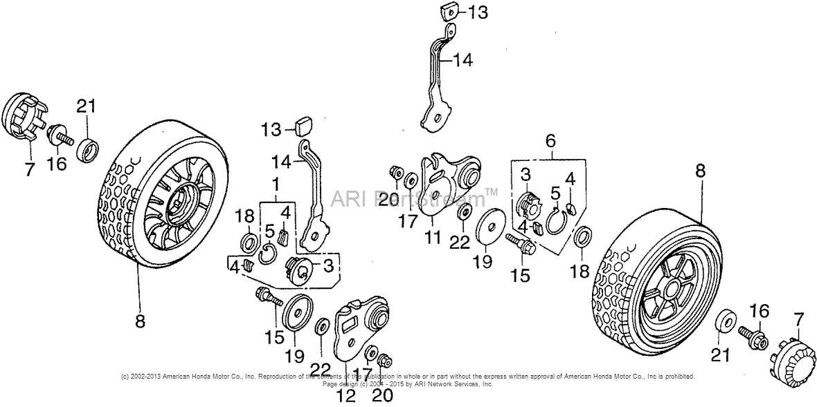
The structure and assembly of the platform and outer casing play a crucial role in the overall functionality and durability of a machine. Understanding these elements is essential for both maintenance and performance enhancement. This section delves into the components involved and their interrelations, providing insights into how they contribute to the efficiency of the device.
Platform Design and Functionality
The platform is typically designed to provide stability and support. It serves as the foundation for other components and must withstand various forces during operation. Materials used in its construction often emphasize strength and resistance to wear, ensuring longevity and reliability.
Outer Casing and Its Importance
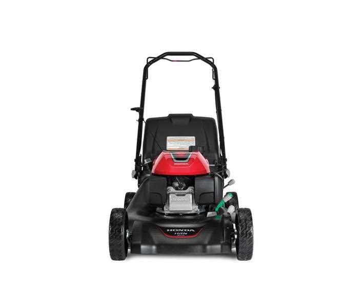
The outer casing not only protects internal mechanisms from external elements but also contributes to the overall aesthetic of the machine. It is essential for safeguarding sensitive components against dust, moisture, and impacts. The design of the casing may include features for easy access to maintenance points, further enhancing usability.
Electrical Wiring and Switch Diagram
This section provides an overview of the electrical connections and switch arrangements essential for efficient operation. Understanding these layouts is crucial for troubleshooting and maintaining optimal functionality of the device.
Below is a representation of the various electrical components and their interconnections:
| Component |
Description |
Connection Type |
| Power Supply |
Source of electrical energy |
AC/DC Input |
| Switch |
Controls the flow of electricity |
Single/Double Pole |
| Fuse |
Protects against overload |
Inline Connection |
| Relay |
Controls high-power circuits |
Coil and Contact |
| Connector |
Joins wires and components |
Terminal Block |
Throttle and Speed Control Components
The effective management of velocity and power is crucial for optimal performance in various machinery. Understanding the elements that contribute to this control allows for enhanced functionality and efficiency. This section delves into the components responsible for regulating the throttle and speed settings in such devices.
- Throttle Control Mechanism: This is the primary system that governs the flow of fuel or energy, influencing acceleration and deceleration.
- Speed Sensors: These instruments monitor the operational speed, providing real-time data to ensure precise adjustments are made as needed.
- Actuators: These devices convert electrical signals into mechanical movement, directly affecting the throttle position and speed settings.
- Control Units: Centralized systems that process inputs from various sensors, enabling automated adjustments to maintain desired performance levels.
- Linkages: These mechanical connections facilitate communication between the throttle control and the engine, ensuring smooth operation.
By comprehensively understanding these components, users can troubleshoot issues more effectively and optimize performance for better results.
Maintenance Parts and Replacement Tips

Ensuring the longevity and efficiency of your equipment involves regular upkeep and timely substitutions of essential components. This section provides guidance on maintaining key elements and offers practical advice for when replacements are necessary.
Essential Components for Regular Upkeep
Routine maintenance can significantly extend the lifespan of your machinery. Focus on checking and cleaning filters, belts, and seals, as these play a crucial role in the overall performance. Regular inspections will help identify any wear or damage, allowing you to address issues before they escalate.
Replacement Guidance for Optimal Performance
When it comes to substitutions, selecting high-quality alternatives is vital for maintaining efficiency. Always refer to the manufacturer’s recommendations for compatible components. Timely replacements not only enhance functionality but also prevent potential breakdowns. Investing in reliable components will yield long-term benefits, ensuring smooth operation and reducing downtime.
Common Issues in Hrn216vka Parts
When dealing with mechanical components, various challenges can arise, impacting functionality and performance. Understanding these common difficulties is essential for maintaining optimal operation.
Frequent Challenges
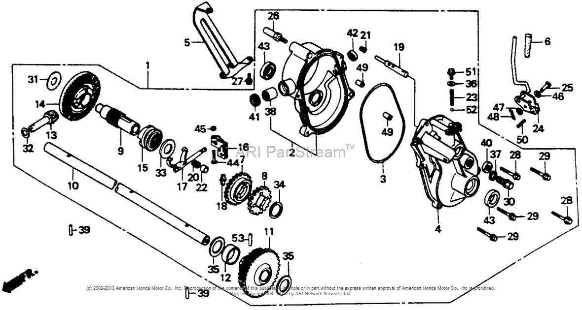
- Wear and Tear: Components may degrade over time, leading to inefficiencies.
- Improper Installation: Incorrect fitting can result in misalignment and malfunction.
- Lack of Maintenance: Neglecting routine checks can exacerbate existing issues.
Signs of Trouble
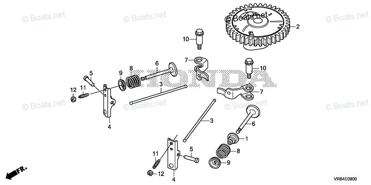
- Unusual Noises: Sounds that deviate from normal operation may indicate underlying problems.
- Decreased Performance: A noticeable drop in efficiency could suggest component failure.
- Visible Damage: Cracks, rust, or other physical defects can compromise functionality.
