The importance of maintaining and understanding the essential elements of your equipment cannot be overstated. Proper knowledge of how each component functions ensures not only smooth performance but also extends the lifespan of the machinery. Identifying key elements and their roles within the system is crucial for any maintenance or repair work.
Comprehensive knowledge of the internal mechanisms allows users to address potential issues before they escalate into significant problems. By familiarizing yourself with the layout and positioning of different components, you can perform routine inspections and detect early signs of wear or malfunction.
Understanding the structural framework and a
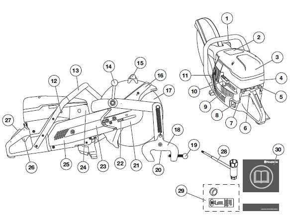
Overview of Husqvarna K1260 Components
Understanding the key elements of this powerful cutting machine is crucial for efficient operation and maintenance. This section provides a breakdown of the core mechanisms and vital structures that work together to deliver optimal performance. Each part plays a specific role in ensuring the device operates smoothly and reliably.
Main Structural Elements
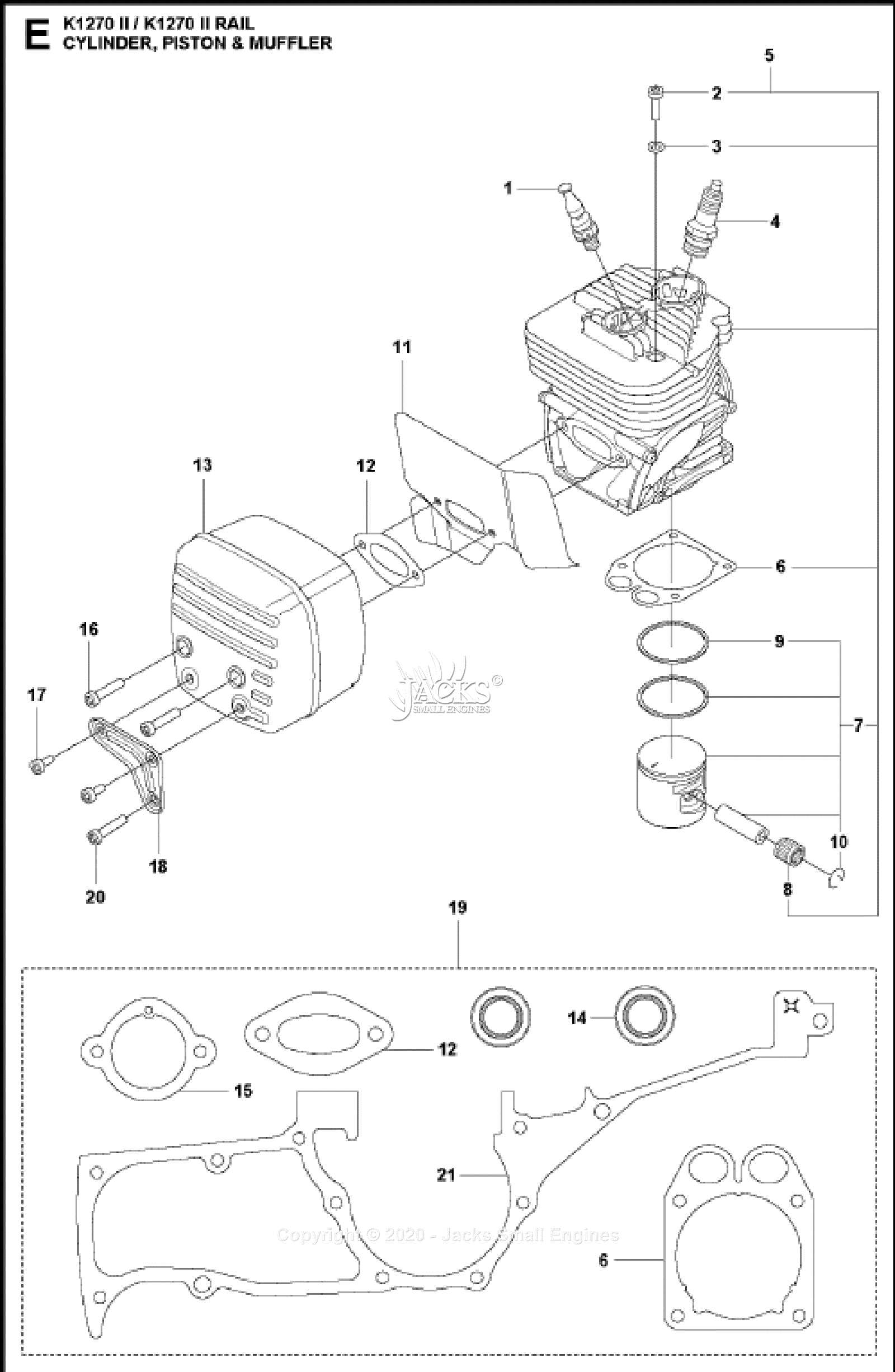
- Engine assembly: The central power source responsible for driving the entire system, ensuring a high level of cutting power.
- Fuel system: A carefully designed network that delivers
Key Features of the Husqvarna K1260
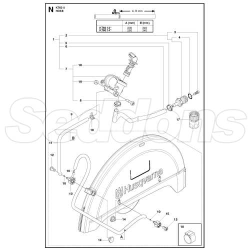
This advanced cutting tool offers a variety of features designed to enhance performance and ensure reliability during demanding tasks. Built for heavy-duty applications, this machine provides efficiency and durability, making it suitable for professional users who require precision and power.
High Performance and Power
Equipped with a high-performance motor, this cutting tool ensures optimal power output, allowing for fast and efficient operation in tough conditions. The enhanced engine design minimizes vibrations and maximizes
Understanding the Engine Assembly
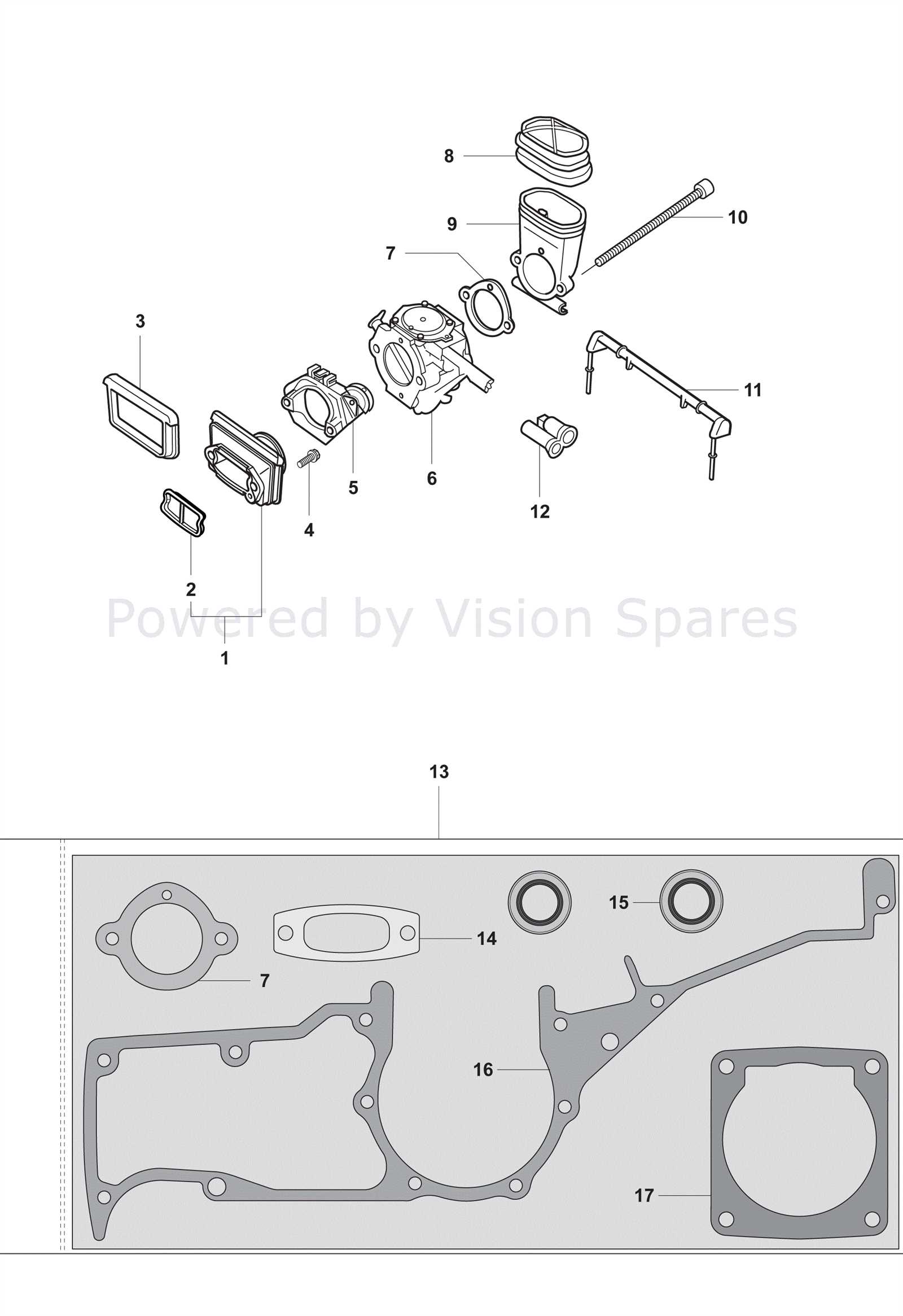
The engine is a complex system that serves as the core component of any cutting tool. Its assembly includes several interconnected elements that work together to ensure smooth and efficient operation. Proper knowledge of how these components interact is essential for maintaining and troubleshooting the system, ensuring longevity and optimal performance.
At the heart of the engine lies a series of mechanical parts designed to generate power and transfer it effectively. From the cylinder and piston to the crankshaft, each piece plays a critical role in converting fuel into the force required to operate the machine. Recognizing the functions of these parts helps in identifying issues and performing maintenance.
Understanding how
Blade Guard and Cutting Mechanism Explained
The blade guard and cutting mechanism are essential components that ensure both safety and efficiency during cutting tasks. Understanding how these elements work together helps to improve the user’s experience and enhances overall control during operation. This section provides a detailed look at the protective shield and the cutting process, offering insights into their key functions.
Function of the Blade Guard
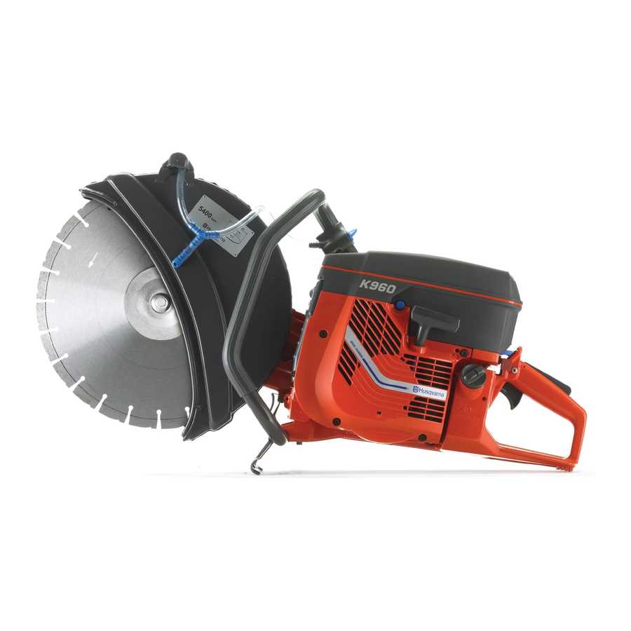
The primary role of the blade guard is to offer protection from debris and prevent accidental contact with the rotating blade. It serves as a barrier that reduces the risk of injury, ensuring safe use even in demanding conditions. The guard
Maintenance Tips for Optimal Performance
Regular care and attention are essential to ensure that your equipment runs efficiently and lasts longer. By following some simple maintenance practices, you can avoid unnecessary wear and ensure smooth operation over time.
Keep It Clean
Dirt, dust, and debris can quickly accumulate and hinder the performance of your tool. Make it a habit to clean the surfaces after each use, paying special attention to the moving parts and ventilation areas. This prevents overheating and ensures smoother operation.
Inspect and Lubricate
Frequent inspection of
How to Replace Air Filters
Regularly replacing the air filter is crucial for maintaining optimal engine performance. The air filter prevents dirt and debris from entering the engine, ensuring clean air is supplied for combustion. Over time, the filter can become clogged, reducing air flow and causing the engine to work harder. This guide outlines the steps to effectively replace the air filter, ensuring your equipment runs smoothly and efficiently.
Tools and Materials Needed
- New air filter
- Screwdriver
- Clean cloth
- Gloves (optional)
Step-by-Step Instructions
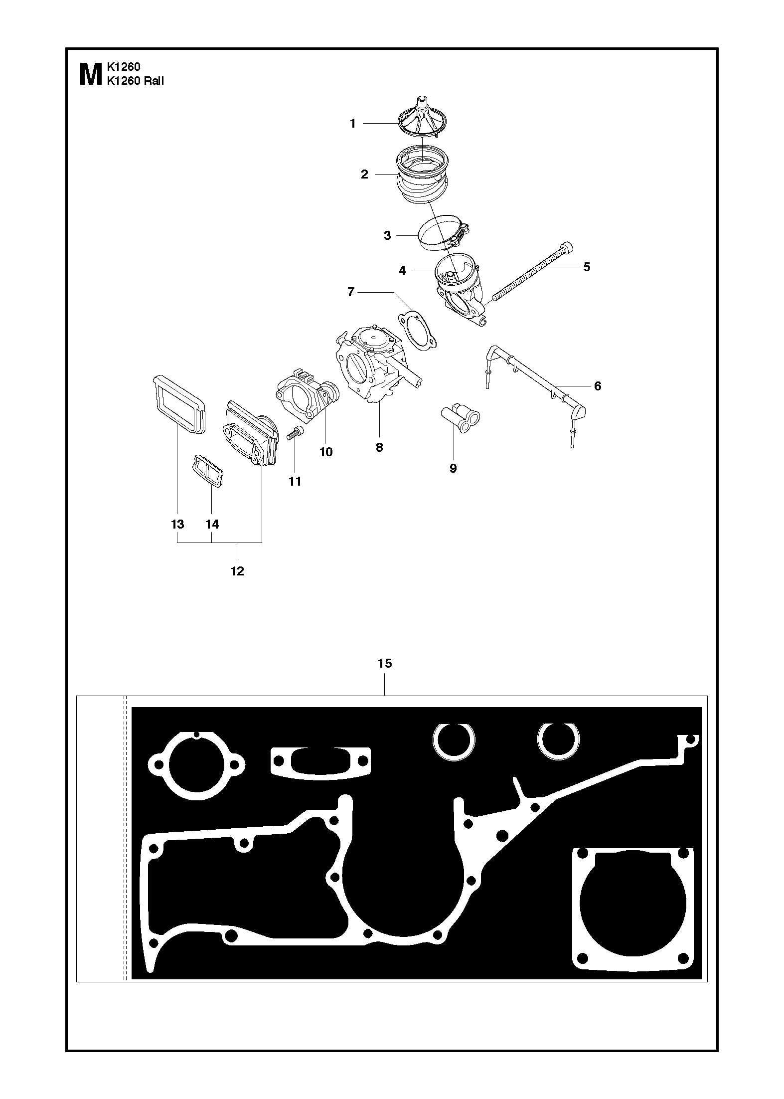
- Turn off the equipment and allow it to cool completely.
- Locate the air filter compartment, usually found on the side of the engine.
- Using a screwdriver, remove any screws or fasteners holding the cover in place.
- Take out the old air filter carefully, ensuring no debris falls into the compartment.
- Clean the area with a cloth to remove any dust or particles.
- Insert the new air filter, making sure it fits snugly and correctly.
- Reattach the cover and tighten the screws to secure it.
- Check the filter’s placement and ensure there are no gaps or loose parts.
By following these steps, you can maintain the air filter’s efficiency, extending the life of your engine and keeping it performing at its best.
Ignition System Parts Overview
The ignition system plays a crucial role in ensuring the efficient operation of high-performance engines. It is responsible for generating and delivering the spark needed to ignite the fuel-air mixture. Understanding the components involved in this system is key to maintaining optimal performance and preventing unnecessary wear and tear on the engine.
Key Components
- Ignition Coil: Converts low voltage from the battery into the high voltage needed to produce a spark at the spark plug.
- Magneto: A device that generates electrical current to power the ignition system, particularly in systems without a battery.
- Spark Plug: Ignites the air-fuel mixture within the combustion chamber, providing the necessary spark for engine operation.
- Flywheel: Often contains magnets that interact with the ignition coil to generate power.
Function and Maintenance
Each of these components must function harmoniously to ensure reliable starting and smooth running of the engine. Regular maintenance, including checking for wear or corrosion in the spark plug and ensuring the ignition coil is working properly, helps prevent performance issues. Understanding the ignition system’s layout and its individual components can simplify troubleshooting and extend the life of the engine.
Fuel System Breakdown and Repair
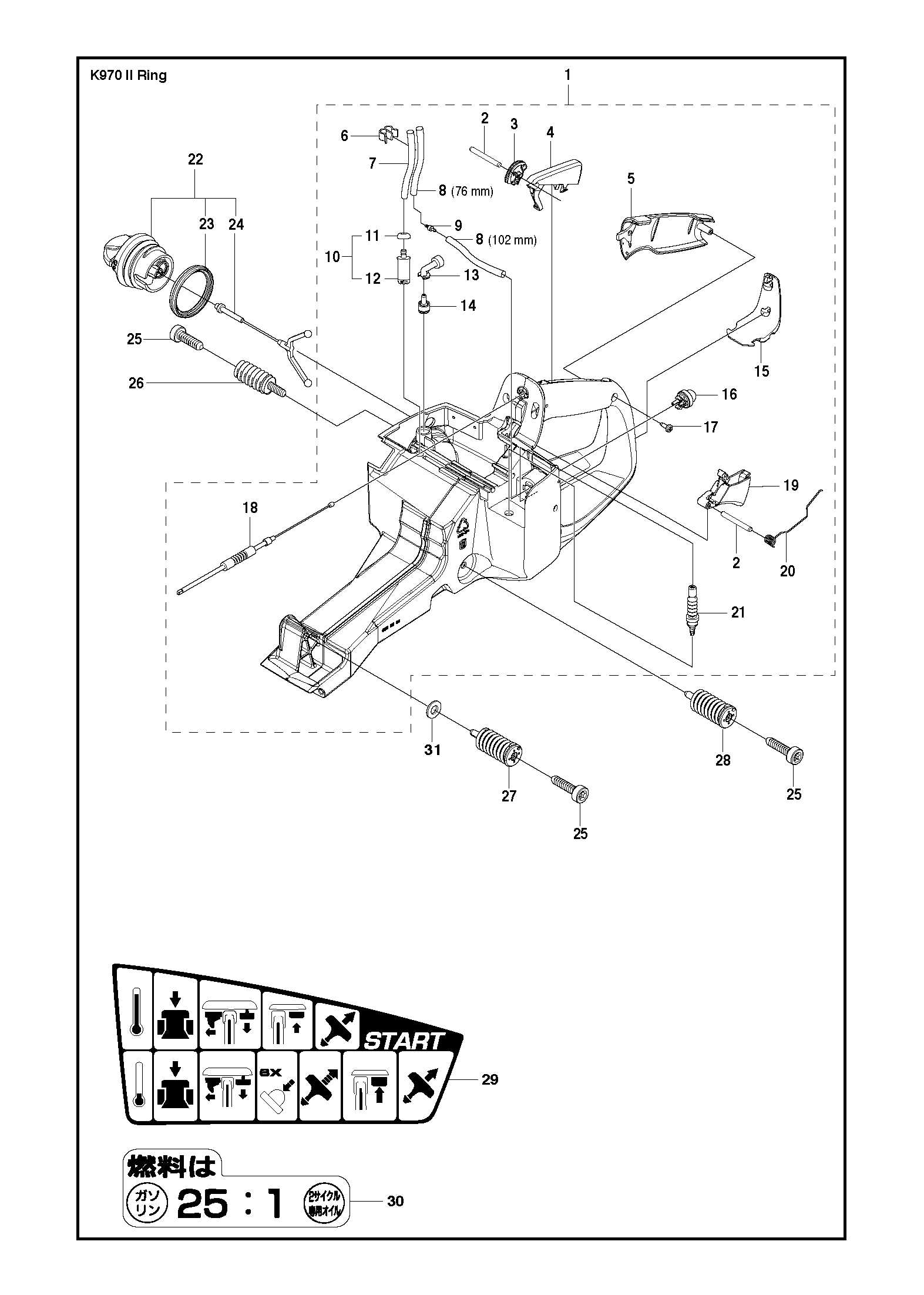
The fuel system plays a vital role in ensuring efficient engine performance. It is responsible for delivering fuel to the combustion chamber in the correct mixture with air. Regular maintenance and understanding of how each component functions can prevent costly repairs and prolong the life of the equipment.
Key components of the fuel system include:
- Fuel tank
- Fuel filter
- Fuel pump
- Carburetor
- Fuel lines
When issues arise, identifying the root cause is essential. Common problems include clogging in the fuel filter, fuel lines, or carburetor, which can lead to poor engine performance, starting difficulties, or stalling during operation.
To repair or maintain the fuel system, follow these steps:
- Inspect the fuel filter: A clogged filter can restrict fuel flow. Replace it if necessary.
- Check the fuel lines: Ensure there are no cracks or blockages. Replace any damaged sections.
- Clean or replace the carburetor: If the carburetor is dirty or damaged, it may not deliver the correct fuel-air mixture, leading to operational issues.
- Test the fuel pump: A malfunctioning pump can prevent fuel from reaching the engine, requiring replacement.
Regularly checking and maintaining the fuel system will ensure smooth operation and prevent future breakdowns.
Guide to Handle and Control Parts
Understanding the components responsible for the operation and maneuvering of cutting equipment is crucial for maintaining performance and ensuring safety. This section will explore the various elements that allow users to manage and control the machine effectively, focusing on the primary controls and handle mechanisms.
Essential Controls for Operation
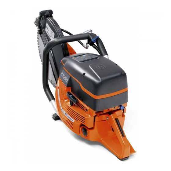
The main control features of any heavy-duty equipment include the throttle, brake, and engagement levers. These are designed to give the user precise control over the machine’s power and movement. Familiarity with these controls is vital for efficient and safe operation.
Component Description Throttle Lever Regulates engine speed, allowing for controlled power delivery during operation. Brake Stops the machine quickly when required, enhancing safety during operation. Engagement Lever Controls the activation of the cutting mechanism, giving the user control over the cutting process. Handle Design and Comfort
The design of the handles is essential for comfort and reducing fatigue during extended use. Ergonomically designed handles allow for better grip and control, while also providing vibration reduction to improve user experience. Proper handle adjustment is key to achieving maximum comfort and efficiency.
Drive Belt and Pulley Functions
The drive belt and pulley system play a crucial role in transferring power from the engine to other components, ensuring smooth operation of the machinery. This system helps maintain the optimal performance of the equipment by efficiently converting rotational motion into the desired mechanical movement.
Drive Belt Mechanics
The drive belt is a flexible, strong component that connects different moving parts. It works by transferring the rotational energy from one pulley to another, allowing for the transmission of power to various mechanical systems. Its elasticity and durability are essential for maintaining the machine’s performance under varying loads and conditions.
Pulley Interaction
Pulleys are wheel-like components that help guide the belt and ensure its correct movement. They play a key role in adjusting the tension of the belt and optimizing the transmission of force. By varying the size and positioning of pulleys, the equipment can achieve different speeds or torque outputs, enhancing its overall versatility.
Troubleshooting Common Part Failures
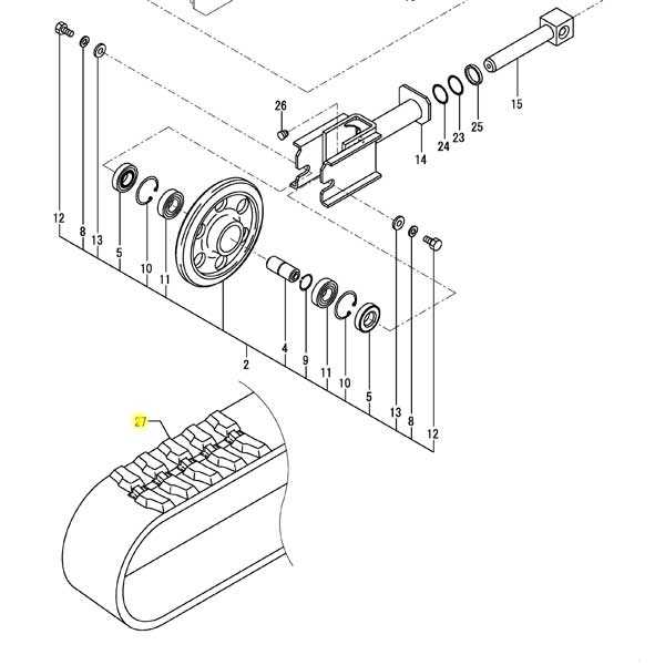
When operating powerful equipment, it’s important to address mechanical issues promptly to ensure optimal performance. Many problems arise due to wear and tear, improper maintenance, or component malfunctions. By understanding common failure points and knowing how to diagnose them, you can avoid costly repairs and downtime.
Engine Misfire or Poor Performance
One of the most frequent issues is a reduction in engine efficiency, which may be caused by faulty fuel delivery or air intake systems. If the engine struggles to start or loses power during use, check for clogged filters, damaged spark plugs, or an improperly adjusted fuel mixture. Ensuring that these components are clean and properly tuned can often resolve the problem.
Excessive Vibration or Unusual Noise
Excessive vibrations or unusual sounds during operation are usually signs of wear on moving parts or imbalanced components. Pay attention to the drive mechanism, as well as the condition of any bearings or bushings. If the equipment produces more noise than usual or vibrates excessively, it’s critical to inspect these elements and replace any worn or broken parts.