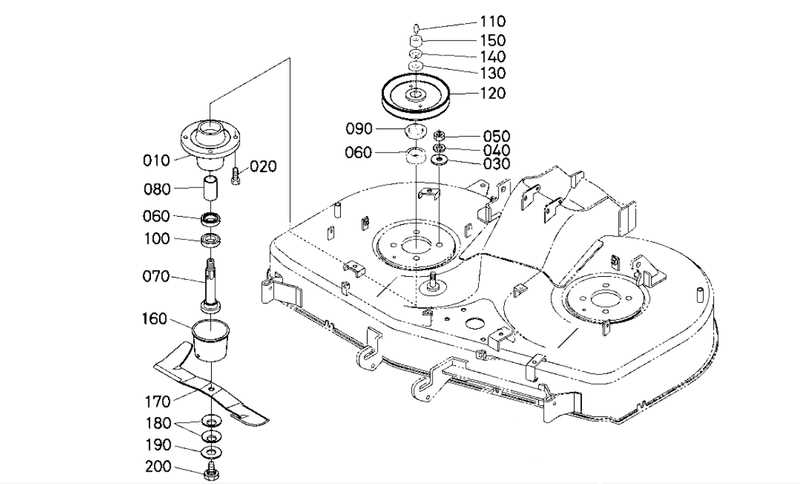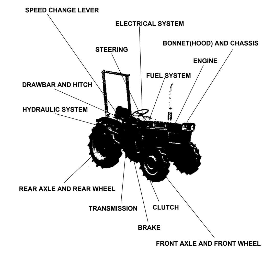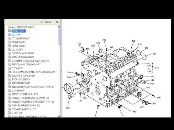
When it comes to maintaining and servicing heavy machinery, a clear visual representation of its components is essential. This resource serves as a valuable tool for operators and technicians alike, enabling them to identify and understand various elements within their equipment. The intricate details provided facilitate better troubleshooting and enhance overall efficiency.
By examining a structured illustration of the machinery, users can quickly pinpoint specific sections and gain insights into their functions. Such visual aids not only simplify the repair process but also promote a deeper understanding of how each part contributes to the ultimate performance of the machine.
Whether you’re a seasoned professional or a newcomer to the field, navigating the complexities of these illustrations can significantly enhance your technical skills. Engaging with this resource allows for a more informed approach to machinery upkeep, ultimately leading to improved operational success.
Kubota Parts Diagram Overview
This section provides a comprehensive look at the visual representation of components used in machinery maintenance and repair. Understanding these illustrations is crucial for anyone involved in servicing equipment, as they highlight the relationship between various elements and aid in identifying specific parts for replacement or troubleshooting.
These graphical depictions serve as essential tools for technicians, providing clarity and organization when it comes to complex assemblies. By breaking down machinery into understandable segments, users can easily navigate the intricacies of their equipment and ensure that repairs are performed efficiently and accurately.
Additionally, these visuals often include part numbers and descriptions, enabling swift identification and procurement of necessary components. Familiarity with these illustrations can significantly reduce downtime, allowing for timely repairs and maintenance that keep operations running smoothly.
In summary, mastering the use of these visual aids is vital for anyone working with machinery, ensuring effective maintenance and enhancing overall operational efficiency.
Understanding Kubota Equipment Models
Recognizing the various models of agricultural machinery is essential for effective operation and maintenance. Each type serves specific purposes and comes with unique features that enhance performance in the field.
Here are key factors to consider when exploring different machinery types:
- Functionality: Identify the primary tasks each model is designed for.
- Specifications: Pay attention to size, power output, and operational capabilities.
- Compatibility: Ensure the equipment can work with various attachments and tools.
- Efficiency: Look for models that maximize productivity while minimizing fuel consumption.
By delving into these aspects, users can make informed decisions and select the ultimate equipment suited for their specific needs.
Importance of Accurate Diagrams

Precise representations are crucial in any technical field, providing a clear visual guide to components and their relationships. These illustrations serve as a foundation for understanding complex systems, facilitating maintenance, assembly, and troubleshooting tasks.
Enhancing Understanding
Clear visuals enable users to quickly grasp the layout and functionality of various elements. By offering detailed views, these representations reduce confusion and improve overall comprehension.
Facilitating Efficient Repairs
Accurate visuals are essential for effective repairs, allowing technicians to locate parts easily and understand their interactions. This efficiency minimizes downtime and maximizes productivity.
| Benefit | Description |
|---|---|
| Clarity | Reduces misunderstandings by providing a clear overview. |
| Efficiency | Speeds up maintenance and repair processes. |
| Training | Serves as a valuable resource for new users learning systems. |
Common Kubota Parts and Their Functions
Understanding the essential components of agricultural machinery is crucial for effective maintenance and optimal performance. Each element plays a specific role, contributing to the overall functionality of the equipment. Familiarity with these components can aid in troubleshooting and enhance operational efficiency.
Key Components
Engine: The heart of the machinery, it converts fuel into mechanical energy, powering all operations. A well-maintained engine ensures reliability and efficiency.
Transmission System
Transmission: This system transfers power from the engine to the wheels. It allows for speed adjustments and maneuverability, critical for various tasks on the field.
By delving into the roles of these vital elements, users can better appreciate the intricate workings of their equipment.
Navigating the Parts Diagrams Online
Understanding complex machinery can be a daunting task, especially when it comes to identifying individual components and their relationships. Fortunately, online resources provide a streamlined approach to exploring these intricate structures, allowing users to easily locate and visualize essential elements. This digital accessibility enhances the ability to maintain and repair equipment effectively.
When accessing these resources, it’s crucial to familiarize yourself with the layout and features of the interface. Many platforms offer interactive views, enabling users to zoom in on specific areas, click on parts for detailed information, and even access installation instructions. Utilizing these tools not only saves time but also helps in gaining a comprehensive understanding of the machinery.
Additionally, leveraging search functionalities can greatly improve efficiency. By entering keywords related to specific components, users can quickly narrow down results, making the process of finding information more straightforward. This targeted approach can enhance productivity, ensuring that you have the right details at your fingertips when needed.
In summary, exploring these online resources offers invaluable support for those looking to deepen their knowledge of machinery components. By mastering the navigation and utilizing available features, users can enhance their repair and maintenance skills significantly.
How to Identify Specific Parts
Recognizing individual components within machinery can seem daunting, but it is crucial for maintenance and repairs. A systematic approach can simplify the identification process, enabling users to locate what they need efficiently.
Steps to Identify Components
- Consult the owner’s manual for reference images and descriptions.
- Use online resources, such as forums and manufacturer websites, for detailed guides.
- Compare the component in question with labeled images or catalogs.
Tips for Accurate Identification

- Take clear photographs of the component from multiple angles.
- Note any serial numbers or model identifiers present on the part.
- Seek assistance from knowledgeable professionals if needed.
Using Diagrams for Maintenance and Repairs
Visual representations are invaluable tools for ensuring effective upkeep and repairs of machinery. These illustrations provide clarity, guiding technicians through complex procedures and helping them identify components with ease. By breaking down intricate systems into understandable segments, users can enhance their troubleshooting capabilities and perform tasks more efficiently.
Benefits of Visual Aids
Employing visual aids during maintenance tasks offers numerous advantages. First, they facilitate a quicker understanding of equipment layouts, enabling technicians to locate specific elements without unnecessary delays. Additionally, these resources minimize the risk of errors by providing precise instructions and highlighting critical connections. Ultimately, the use of such tools promotes a more systematic approach to repair work.
Improving Efficiency with Clear Guidance
When technicians refer to visual representations, they can streamline their workflow. Effective illustrations serve as a reference point, allowing users to follow steps in a logical order. This organized method reduces the likelihood of missing crucial details and enhances overall productivity. Furthermore, by making maintenance tasks clearer, these guides empower users to take on challenges with greater confidence.
Where to Find Official Diagrams
Accessing accurate illustrations and technical schematics for machinery components is crucial for effective maintenance and repair. Fortunately, there are several reliable sources where you can obtain these essential visuals.
- Manufacturer Websites: Most manufacturers provide a dedicated section for service resources, including detailed illustrations.
- Authorized Dealers: Visiting or contacting authorized dealers can yield access to official materials, often accompanied by expert advice.
- Service Manuals: Purchasing or downloading official service manuals usually includes comprehensive visuals and specifications.
- Online Forums: Engaging in community forums can connect you with experienced users who share valuable resources.
Exploring these avenues will ultimately enhance your understanding and facilitate effective repairs.
Tips for Interpreting Technical Drawings

Understanding complex illustrations can greatly enhance your ability to work with machinery and equipment. By mastering the interpretation of these visuals, you can ensure efficient assembly, maintenance, and troubleshooting. Here are some essential tips to guide you through the process.
Familiarize Yourself with Symbols
Technical visuals often utilize specific symbols. Knowing these can save time and prevent errors. Here are common symbols you might encounter:
- Circles for connections
- Lines for movement paths
- Shaded areas for specific components
Analyze the Scale
Understanding the scale is crucial for accurate interpretation. Here are some strategies:
- Check the scale ratio indicated on the drawing.
- Use a ruler to measure components against the scale.
- Compare with real-world objects for perspective.
By following these tips, you can delve deeper into the information presented and enhance your ultimate understanding of the material.
Comparing OEM and Aftermarket Parts
When it comes to maintaining machinery, the choice between original equipment and alternative components is crucial. Each option has distinct advantages and potential drawbacks, impacting both performance and budget. Understanding these differences helps in making informed decisions that can ultimately affect the longevity and efficiency of your equipment.
Quality and Performance
Original components are often designed to meet the highest standards set by manufacturers, ensuring compatibility and reliability. Aftermarket options, on the other hand, can vary widely in quality. While some may offer similar performance, others might not uphold the same durability, leading to potential issues down the line. Researching reputable brands is essential when considering alternatives.
Cost Considerations
Price is a significant factor in this comparison. While original components generally come with a higher price tag, they often provide peace of mind and warranty coverage. Alternative components can be more budget-friendly, yet it’s vital to weigh the potential risks of lower quality against the savings. Ultimately, assessing your specific needs and long-term goals will guide you toward the best choice.
Cost Implications of Using Diagrams
Utilizing visual representations for components can significantly influence financial outcomes in maintenance and repair activities. By offering clarity and precision, these illustrations help in minimizing errors and optimizing resource allocation, ultimately impacting the bottom line.
Benefits of Visual Aids
- Reduced downtime through quick identification of necessary elements.
- Lowered labor costs due to increased efficiency.
- Improved training outcomes, leading to less costly mistakes.
Potential Drawbacks
- Initial investment in quality resources can be substantial.
- Dependence on visuals may lead to neglect of hands-on experience.
- Inaccurate or outdated illustrations can cause confusion and additional expenses.
Real-Life Applications of Parts Diagrams
The use of visual representations in mechanical fields plays a crucial role in understanding the assembly and functionality of various components. These illustrations serve as essential tools for technicians and engineers, enhancing efficiency and accuracy during repairs and maintenance.
One significant application is in the training of new employees. Visual aids help novices grasp complex systems quickly, allowing them to familiarize themselves with different elements and their interactions. This foundational knowledge can lead to increased confidence and proficiency on the job.
Additionally, these visuals are invaluable during troubleshooting. When issues arise, having a clear representation of the components involved aids in identifying potential failures. Technicians can easily pinpoint the specific area that requires attention, streamlining the repair process and minimizing downtime.
Furthermore, these illustrations facilitate effective communication among team members. When discussing specific issues or modifications, referring to a shared visual reference ensures everyone is on the same page, reducing misunderstandings and enhancing collaboration.