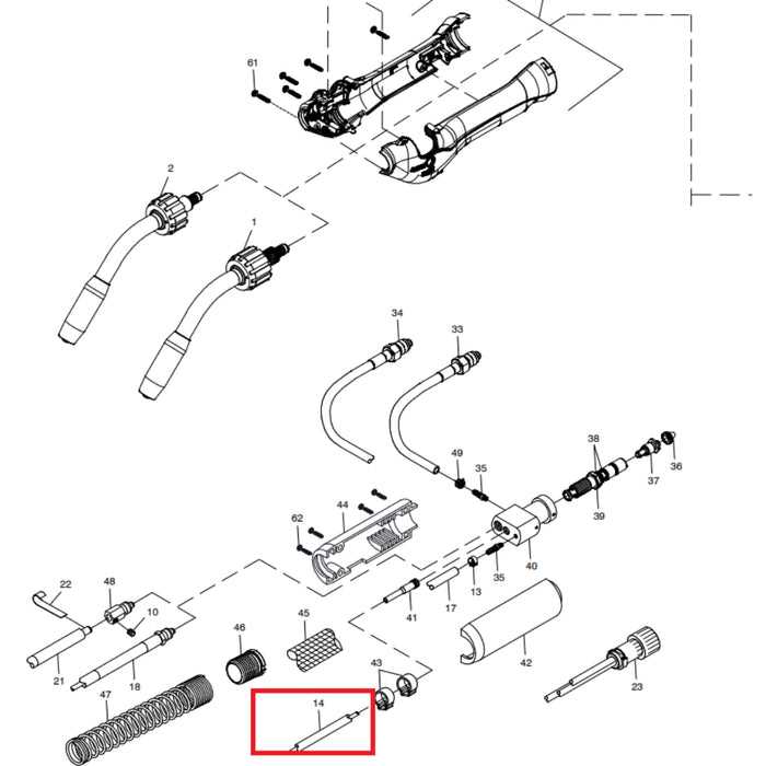
When delving into the intricacies of a welding apparatus, it becomes essential to familiarize oneself with the various elements that contribute to its functionality. Each component plays a vital role in ensuring optimal performance, making knowledge of their layout and interconnections crucial for both novices and experienced users alike.
A comprehensive overview of these mechanisms allows for better troubleshooting and maintenance, enhancing the overall efficiency of the equipment. By grasping how these individual parts interact, operators can make informed decisions regarding repairs or upgrades, ultimately extending the lifespan of their device.
Moreover, understanding the arrangement of these elements can simplify the learning process for those new to welding. With clear insights into how each piece contributes to the operation, users can cultivate their skills more effectively, paving the way for successful projects and improved craftsmanship.
Key Components of a MIG Welder
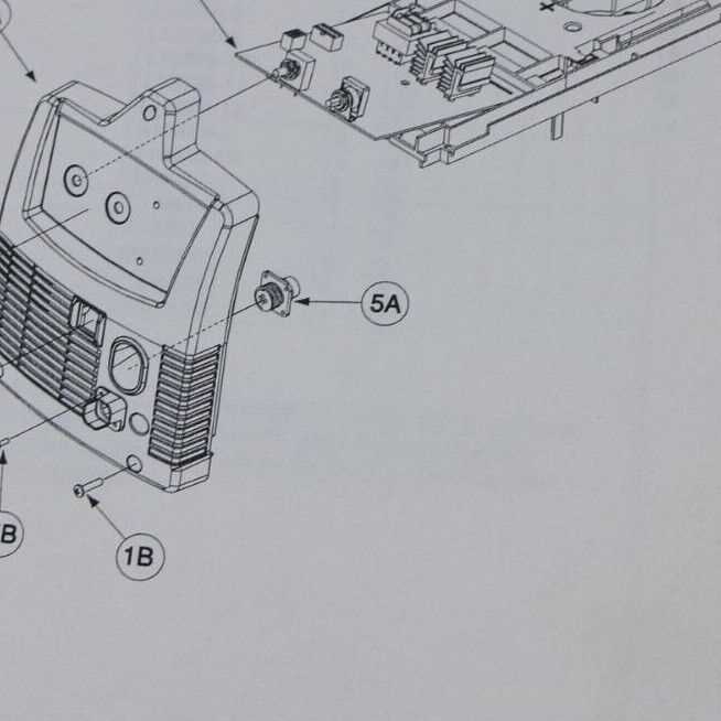
The efficient operation of a metal joining machine relies on several essential elements. Understanding these crucial components is vital for both maintenance and optimal performance. Each part plays a specific role in ensuring that the process runs smoothly, delivering high-quality results.
Essential Elements of the System
Among the most important elements are the feed mechanism, which supplies the filler material, and the power source that provides the necessary energy for melting. Additionally, protective features are crucial to safeguard both the user and the equipment from potential hazards.
Functions of Each Component
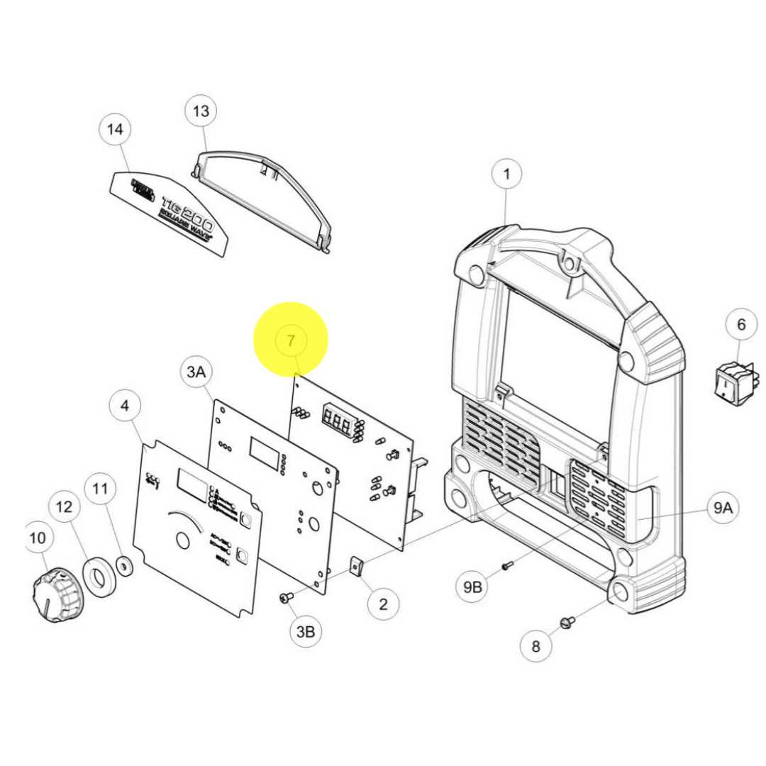
Each part not only contributes to the overall function but also enhances the reliability and quality of the output. For instance, a well-designed nozzle ensures proper gas flow, while a sturdy housing protects internal mechanisms from external damage.
| Component | Function |
|---|---|
| Feed Mechanism | Supplies filler material to the welding area. |
| Power Source | Provides energy for melting the materials. |
| Nozzle | Regulates gas flow for shielding. |
| Control Panel | Allows the operator to adjust settings. |
| Safety Features | Protects users from electrical and thermal hazards. |
Understanding the Welding Torch Assembly
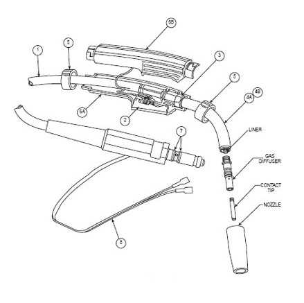
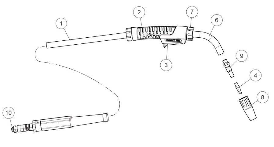
The welding torch assembly is a crucial component in the welding process, playing a significant role in ensuring quality and efficiency. This unit typically consists of several interconnected parts that work together to deliver heat and control the welding operation.
Key components of the torch assembly include:
- Handle: The part that the operator holds, designed for comfort and control.
- Nozzle: Directs the flow of heat and shielding gas to the workpiece.
- Electrode: The consumable part that provides the filler material for the joint.
- Gas supply line: Transports the shielding gas from the source to the nozzle.
- Trigger mechanism: Activates the flow of gas and current when pressed.
Each element of the torch assembly must be maintained properly to ensure optimal performance. Regular inspection and replacement of worn or damaged components are essential for achieving the desired welding results.
The Role of the Wire Feed Mechanism
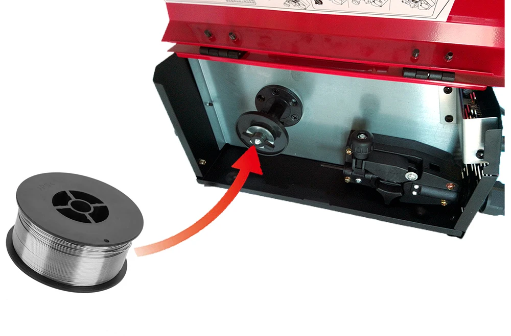
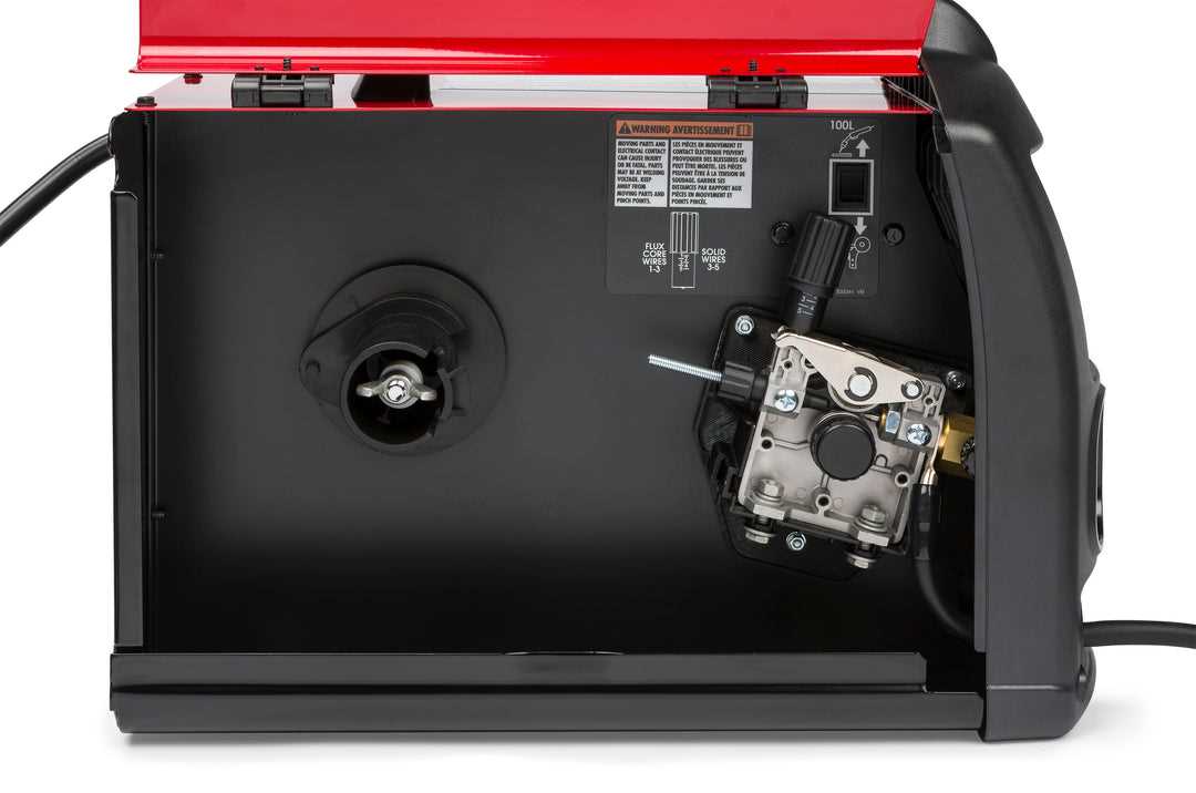
The wire feed mechanism is a crucial component in the functioning of various arc welding systems. It ensures a consistent and controlled supply of filler material, which is essential for creating strong and durable welds. This mechanism plays a vital part in maintaining the efficiency and effectiveness of the welding process, allowing for smoother operation and higher quality results.
In essence, this system utilizes a series of rollers and drives to pull the wire from a spool and deliver it to the welding torch at a predetermined rate. By regulating the speed of the wire feed, it enables the welder to adapt to different materials and thicknesses, enhancing versatility in various applications. The precise delivery of the filler material is critical for achieving optimal weld penetration and fusion.
Moreover, the wire feed mechanism contributes to the overall stability of the welding arc. A steady and uninterrupted supply of wire helps to minimize fluctuations in the arc length, which can lead to inconsistent welds. This consistency not only improves the appearance of the welds but also enhances their mechanical properties, making them more resilient to stresses and environmental factors.
Gas Flow Control and Its Importance
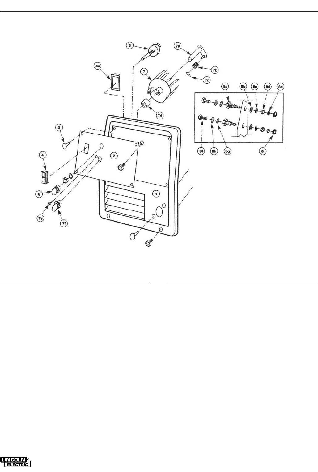
Proper management of gas flow is crucial in various applications where welding or similar processes are employed. This control ensures optimal performance and enhances the quality of the final output. By regulating the amount of gas, users can significantly influence the stability and effectiveness of the operation.
Inadequate gas flow can lead to various issues, such as poor weld quality, excessive spatter, and even damage to the equipment. Maintaining the right flow not only improves the integrity of the weld but also contributes to safety by minimizing the risk of defects.
| Factor | Impact of Improper Gas Flow |
|---|---|
| Weld Quality | Poor bonding and strength |
| Spatter | Increased material cleanup |
| Equipment Damage | Higher maintenance costs |
| Safety | Increased risk of accidents |
In summary, effective control of gas flow is essential for achieving high-quality results, ensuring equipment longevity, and enhancing overall safety in welding processes.
Power Supply Connections Explained
Understanding the connections associated with the power supply is crucial for ensuring optimal performance and safety in your equipment. These connections provide the necessary energy to operate the machine efficiently and reliably.
Types of Connections
Power supply systems typically involve several types of connections. Here are the most common:
- Input Connections: These links bring power from the source to the device.
- Output Connections: These deliver the energy to the various components within the machine.
- Ground Connections: Essential for safety, these ensure the device is properly grounded to prevent electrical hazards.
Connection Tips
When handling power supply connections, consider the following guidelines:
- Always ensure that the device is powered off before making any connections.
- Verify that all connections are secure to avoid potential issues.
- Consult the manual for specific instructions related to your equipment.
Maintenance of Drive Rollers
Ensuring the longevity and efficiency of drive rollers is essential for optimal performance in welding equipment. Regular upkeep not only enhances functionality but also prevents potential issues that could disrupt the welding process.
To maintain the drive rollers effectively, consider the following key practices:
| Maintenance Task | Frequency | Description |
|---|---|---|
| Visual Inspection | Weekly | Check for wear, damage, and proper alignment. |
| Cleaning | Monthly | Remove debris and contaminants to ensure smooth operation. |
| Lubrication | Every 3 months | Apply appropriate lubricant to reduce friction and wear. |
| Adjustment | As needed | Ensure rollers are properly tensioned and aligned. |
By adhering to these maintenance recommendations, users can significantly extend the life of their drive rollers and maintain consistent performance.
Exploring the Function of Contact Tips
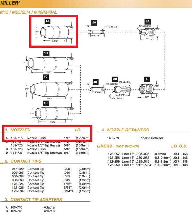
Contact tips play a crucial role in ensuring optimal performance in various welding applications. They serve as a conductive element, facilitating the transfer of electricity between the welding machine and the material being worked on. Understanding their function and significance can enhance the quality and efficiency of the welding process.
Key Characteristics of Contact Tips
These components are typically made from highly conductive materials, which enable them to withstand the high temperatures generated during welding. Their design is tailored to accommodate different welding wire diameters and materials, ensuring a stable arc and minimizing spatter. Proper selection and maintenance of contact tips are essential for achieving consistent results.
Impact on Welding Quality
The condition of contact tips directly affects the quality of the weld. Worn or damaged tips can lead to poor electrical conductivity, resulting in erratic arcs and incomplete welds. Regular inspection and timely replacement of these components are vital practices for welders aiming to maintain high standards in their work.
Welding Cables and Their Specifications
In the realm of fabrication and assembly, the quality and type of cables employed play a crucial role in ensuring efficient and safe operations. Understanding the characteristics of these cables is essential for achieving optimal performance during the joining of materials.
Types of Welding Cables
Various types of cables are utilized in the welding process, each designed to meet specific requirements and applications. The most common types include:
- Power Cables: Designed to carry electrical current to the welding equipment.
- Ground Cables: Ensure a safe electrical connection between the workpiece and the equipment.
- Electrode Cables: Facilitate the transfer of electrical current to the welding rod.
Key Specifications
When selecting welding cables, several specifications must be considered to ensure compatibility and safety:
- Wire Gauge: Indicates the thickness of the cable, impacting current-carrying capacity.
- Insulation Material: Affects durability and resistance to heat, abrasion, and chemicals.
- Length: Determines the range of movement and accessibility during the welding process.
Importance of Cooling Systems in Welders
The efficiency and longevity of welding equipment greatly depend on effective cooling mechanisms. High temperatures generated during operations can lead to overheating, which negatively impacts performance and may even cause damage. Therefore, understanding the significance of cooling systems is essential for maintaining optimal functionality and ensuring safety during the welding process.
Preventing Overheating
One of the primary functions of cooling systems is to regulate temperatures within the apparatus. By dissipating heat effectively, these systems prevent overheating that can lead to component failure or reduced productivity. Proper cooling not only enhances the performance of the equipment but also extends its lifespan, allowing users to achieve better results over time.
Enhancing Operational Safety
In addition to improving performance, cooling systems play a vital role in ensuring the safety of the welding process. Excessive heat can pose risks such as burns or fires, making it crucial to implement adequate cooling solutions. By maintaining safe operating temperatures, these systems contribute to a safer working environment, protecting both the equipment and the operators involved.
Common Issues with MIG Welder Nozzles
Nozzles play a crucial role in the operation of any wire-feed welding system. Over time, they are prone to various problems that can affect the quality and efficiency of the work. These issues often stem from improper handling, lack of maintenance, or exposure to harsh conditions during use.
Clogging and Debris Build-Up
One of the most frequent problems is the accumulation of spatter and debris inside the nozzle. This can obstruct gas flow, resulting in poor welds. Regular cleaning and inspection are essential to prevent this build-up
Guide to Proper MIG Gun Maintenance
Maintaining your welding tool is essential for consistent performance and longevity. Regular upkeep prevents issues that may disrupt your work, ensuring smooth operation and minimizing the need for repairs. Proper care will also extend the lifespan of components, making your equipment more reliable and cost-effective over time.
Cleaning and Inspection
Routine cleaning is a key aspect of keeping your welding tool in good condition. Dirt, debris, and residue can accumulate, causing blockages or wear. Inspect your equipment regularly to check for signs of damage or wear on critical parts, ensuring all components are functioning as intended.