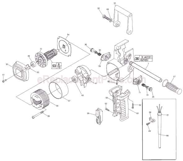
Understanding the structure and internal mechanisms of power tools is crucial for anyone looking to ensure longevity and optimal performance. Having a clear view of the assembly of each part within a tool allows for easy identification of worn or damaged elements, aiding in maintenance and repair.
This section explores the breakdown of key elements found in power equipment used for various tasks. By providing detailed insights into the arrangement of these components, users can better grasp how the internal workings contribute to overall functionality and precision.
Through an examination of the connections and placement of individual sections, we aim to guide users in navigating repairs or replacements with confidence, ensuring smooth operation and enhanced efficiency in their projects.
Power Tool Overview
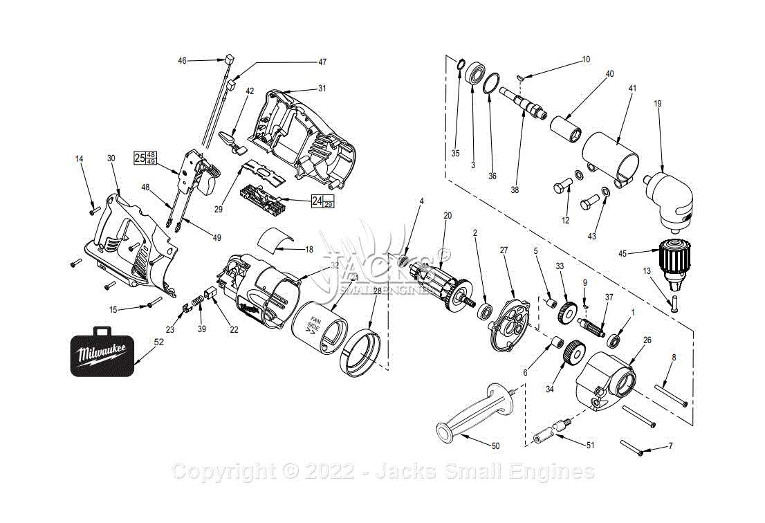
In this section, we delve into the intricacies of a specialized tool designed for precise operations in tight spaces. This device embodies robust engineering, offering versatility and ergonomic design to enhance user experience. The mechanism ensures efficient performance, featuring a compact configuration suited for various applications. Its construction integrates durable components, emphasizing longevity and reliability under demanding conditions. This tool represents innovation in tool technology, catering to professionals seeking optimal functionality in confined workspaces. Emphasizing ease of use and operational efficiency, it remains a staple in the toolkit of professionals across diverse industries.
Main Components of a Right Angle Drill
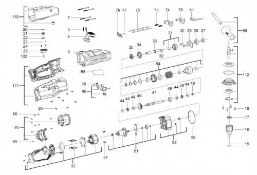
In power tools designed for challenging spaces, specific elements come together to ensure precision, control, and efficiency. Understanding these elements is essential for optimal use and maintenance. Each part plays a key role in ensuring the tool functions seamlessly, offering the user versatility and ease in various tasks.
Motor Assembly
The motor is the heart of the tool, responsible for converting electrical energy into mechanical motion. Its power determines how effectively the tool can handle different materials, from wood to metal. This component often comes with ventilation features to prevent overheating, ensuring durability during prolonged use.
Chuck Mechanism
The chuck is the part that holds the working accessory, such as bits or attachments. It ensures a firm grip on the chosen tool, preventing slippage during operation. Adjustable chucks allow for easy swapping of accessories, making the tool adaptable to various tasks and materials.
Understanding the Gear Mechanism
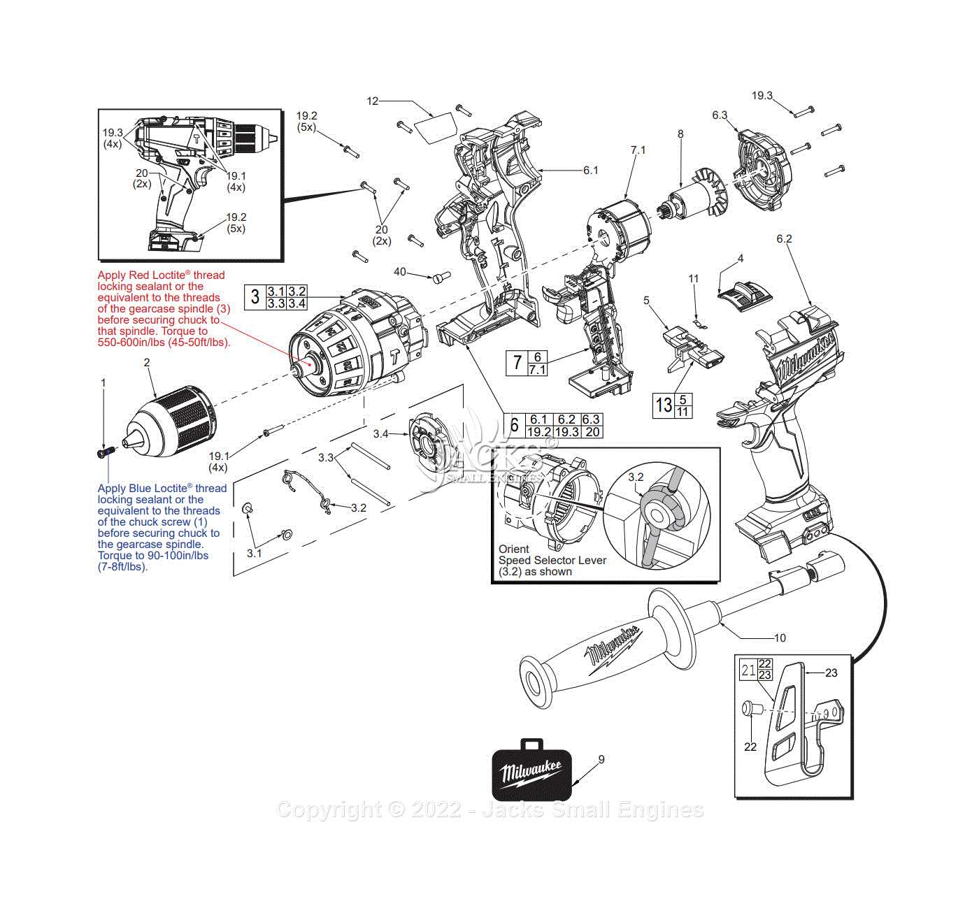
The gear system is a crucial component that ensures the smooth operation of any mechanical tool. It helps regulate speed, control torque, and manage the overall efficiency of the device. In this section, we will explore the different elements of this system and how they interact to create a balanced and efficient performance.
- Gears: These rotating elements transfer motion between components, altering speed or force as needed.
- Housing: This part protects the inner workings of the mechanism, ensuring durability and long-term operation.
- Bearings: Positioned around the gears, bearings minimize friction and allow for smooth movement.
- Axle: The axle serves as the main shaft, transmitting the power generated by the gears to other parts of the tool.
Understanding how each of these elements functions together can help in maintaining the tool’s longevity and diagnosing any performance issues that may arise.
Motor and Power Source Diagram
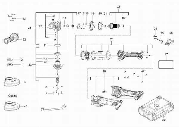
The section provides a comprehensive overview of how the internal mechanism and energy supply system interact to drive the tool. By understanding the relationship between these components, users can better diagnose issues and ensure the device functions efficiently.
| Component | Description |
|---|---|
| Electric Motor | Responsible for converting electrical energy into mechanical force to rotate the drill’s bit. |
| Power Supply | Provides the necessary voltage and current to the motor, ensuring consistent operation. |
| Wiring System | Connects the power source to the motor, allowing for the controlled flow of electricity. |
| Control Switch | Regulates the power flow, enabling the user to start and stop the tool as needed. |
Trigger and Speed Control Assembly
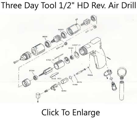
The trigger and speed control system plays a crucial role in managing the functionality and performance of the tool. This assembly allows users to adjust the operational pace based on the specific requirements of the task at hand, ensuring precision and efficiency. It is designed to provide seamless control, enhancing both user experience and safety.
Trigger Mechanism: The trigger acts as the primary activation point, allowing the user to start and stop the device effortlessly. Its ergonomic design ensures comfortable operation, even during extended use. The sensitivity of the trigger allows for incremental adjustments to speed, offering greater control over the tool’s power.
Speed Control System: The integrated speed control feature provides variable speed settings, enabling the user to adapt to different materials and tasks. By offering a range of speeds, the system ensures versatility, helping to maintain optimal performance regardless of the complexity of the task. This control mechanism is crucial for achieving smooth and precise results.
Chuck and Bit Holder Structure
The chuck and bit holder play a crucial role in securing various types of bits during operation. They ensure that the tool maintains a strong grip on the bit, allowing for efficient and accurate work. The design of these components is vital for both stability and versatility, accommodating different sizes and shapes of bits.
| Component | Function |
|---|---|
| Chuck | Secures the bit in place, allowing for precise control and stability during use. |
| Bit Holder | Holds the bit securely, preventing slippage while enabling quick changes between bits. |
| Locking Mechanism | Ensures that the bit is tightly held, providing additional safety and control during use. |
| Adjustment Collar | Allows for easy tightening or loosening of the chuck, facilitating efficient bit changes. |
Electrical Wiring and Circuitry Layout
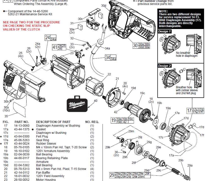
The arrangement of electrical connections and the overall circuitry layout are crucial components in ensuring efficient operation and safety of power tools. Understanding these elements allows users to effectively troubleshoot issues and optimize performance, while also facilitating maintenance and repairs.
Key Components of Electrical Systems
- Power Source: The origin of electrical energy, which can be either battery-operated or mains supply.
- Wiring: Conductors that transmit electrical current between various components.
- Switches: Devices that control the flow of electricity, enabling or disabling functionality.
- Connectors: Elements that link different wires and components together, ensuring a secure and efficient electrical path.
Circuit Design Principles
Creating an effective circuitry layout involves several fundamental principles:
- Safety: Ensure all connections are properly insulated and secure to prevent shorts or electrical hazards.
- Efficiency: Minimize resistance and energy loss by optimizing the routing of wires and selecting appropriate gauge.
- Accessibility: Design layouts that allow for easy access to components for maintenance and repairs.
Handle and Grip Design Features
The design of handles and grips plays a crucial role in the overall functionality and user experience of tools. A well-crafted grip enhances control, reduces fatigue, and ensures safety during operation.
- Ergonomic Shape: Curved contours that fit the natural hand position.
- Material Selection: Use of rubber or textured surfaces for better traction.
- Size Variability: Different dimensions to accommodate various hand sizes.
- Shock Absorption: Features that minimize vibrations during use.
- Grip Patterns: Textured designs that prevent slippage.
Incorporating these elements leads to an ultimate improvement in handling and overall performance, allowing users to delve deeper into their projects with confidence and ease.
Internal Bearings and Shaft Connections
The functionality of power tools often relies on intricate assemblies that ensure smooth operation and efficient performance. Among these critical components, the internal bearings and shaft connections play a vital role in minimizing friction and maximizing torque transfer. Understanding their configuration can greatly enhance maintenance and repair efforts.
Role of Internal Bearings
Internal bearings serve as essential elements that facilitate rotational motion. Their primary functions include:
- Reducing friction between moving parts
- Supporting shafts and ensuring alignment
- Absorbing radial and axial loads
Various types of bearings can be utilized, each suited for specific applications and performance requirements. The choice of bearing affects both durability and efficiency.
Shaft Connections Overview
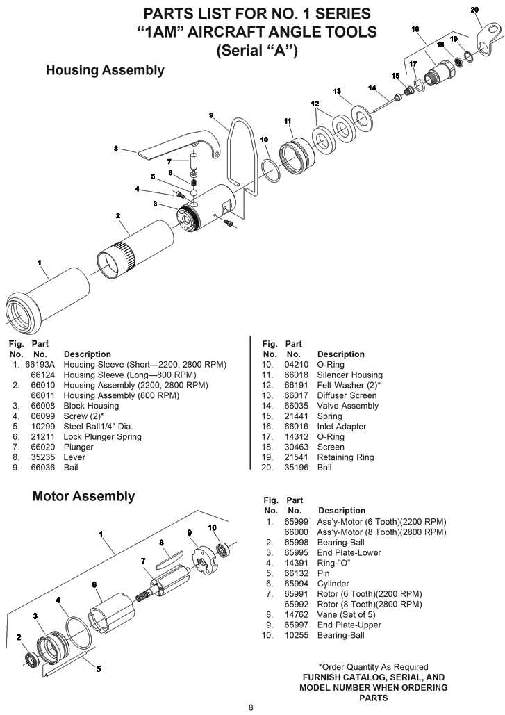
The connections between shafts and other components are crucial for effective power transmission. Key aspects include:
- Types of Connections: Common configurations include keyed, splined, and threaded connections.
- Alignment: Proper alignment is essential to avoid undue wear and ensure optimal performance.
- Material Selection: The materials used can impact the strength and longevity of the connections.
Understanding these elements can lead to better troubleshooting practices and enhance the overall lifespan of the equipment.
Maintaining and Replacing Key Parts
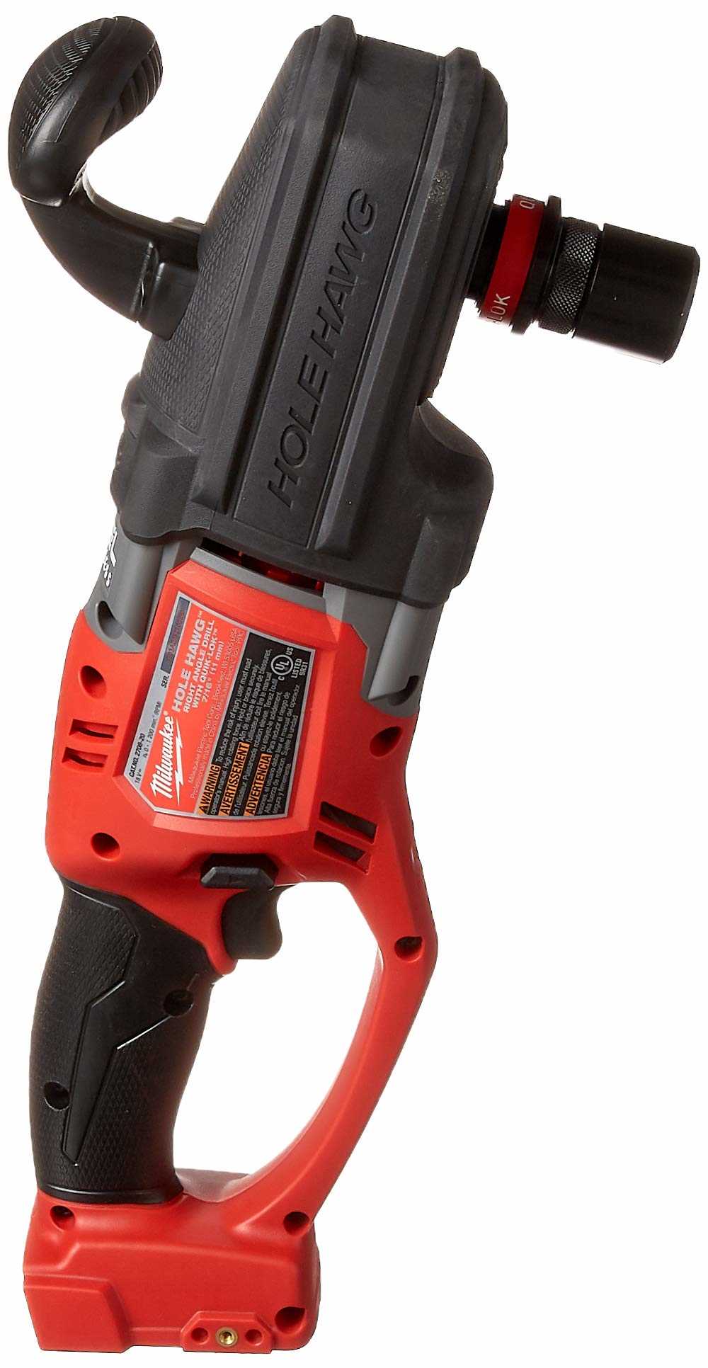
Proper upkeep and timely replacement of essential components are crucial for ensuring optimal performance and longevity of your tool. Regular inspections can help identify wear and tear, allowing for proactive measures to be taken before significant issues arise. Understanding how to care for and replace these elements will not only enhance efficiency but also promote safety during operation.
Key elements that often require maintenance include the motor, gear assembly, and chuck. Each of these components plays a vital role in the overall functionality, and neglecting them can lead to decreased effectiveness or even potential hazards. Familiarity with these parts will empower users to address minor issues independently, thus saving time and resources.
| Component | Signs of Wear | Maintenance Tips | Replacement Advice |
|---|---|---|---|
| Motor | Overheating, unusual noises | Keep clean, check ventilation | Consult manual for specific model |
| Gear Assembly | Slipping, grinding sounds | Regular lubrication, check alignment | Replace with OEM parts |
| Chuck | Difficulty gripping bits, wobbling | Clean regularly, check for debris | Ensure compatibility when replacing |
Common Issues with Drill Parts
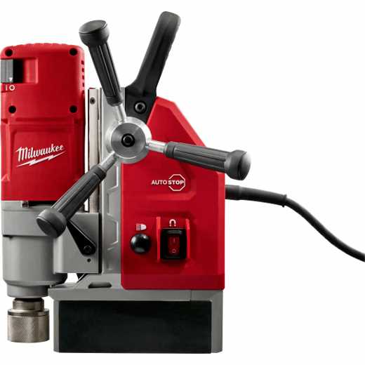
Power tools often encounter various challenges that can hinder their performance and longevity. Understanding these common problems is crucial for effective maintenance and troubleshooting. Users should be aware of potential signs indicating that components may require attention or replacement.
| Issue | Symptoms | Possible Solutions |
|---|---|---|
| Overheating | Excessive heat, reduced efficiency | Check for blockages, ensure proper lubrication |
| Excessive Vibration | Unusual shaking, difficulty controlling | Inspect for loose components, replace worn parts |
| Poor Performance | Inconsistent power, slow operation | Clean or replace filters, check motor function |
| Battery Issues | Short usage time, failure to charge | Test battery health, replace if necessary |