Exploring the intricate elements that contribute to the functionality of mechanical systems is essential for both enthusiasts and professionals. A comprehensive overview of these components reveals their interconnected roles in ensuring optimal performance.
Visual representations play a crucial role in grasping the relationships between various segments. By examining these illustrations, one can gain insights into the mechanics behind movement and energy transfer.
Ultimately, a deep understanding of these essentials not only enhances maintenance and repair efforts but also fosters a greater appreciation for engineering innovation. Let us delve into the fascinating world of machinery anatomy.
Understanding Motor Parts Diagrams
Comprehending the intricate layouts of mechanical components is essential for anyone involved in the field. These visual representations serve as guides, helping users identify and understand the relationships between various elements within a system. Mastery of these illustrations enhances both troubleshooting and assembly processes.
Importance of Visual Aids
Visual aids play a crucial role in simplifying complex machinery. By providing a clear overview, they enable individuals to quickly locate and analyze key components. This ultimately facilitates better maintenance and efficient repairs.
Key Elements to Recognize
When examining these illustrations, focus on labels, symbols, and connections. Understanding these elements allows for deeper insights into functionality and enhances one’s ability to navigate the system effectively. Delving into each section reveals the ultimate harmony within the machinery.
Importance of Motor Parts Diagrams
Visual representations of machinery components play a crucial role in understanding their intricate relationships and functions. By simplifying complex systems, these illustrations serve as invaluable tools for both learning and practical application, ensuring efficiency and accuracy in maintenance and assembly processes.
Enhancing Understanding
Clear visuals allow technicians and enthusiasts alike to quickly grasp the arrangement and operation of various elements. This enhances problem-solving capabilities, enabling users to pinpoint issues more effectively.
Facilitating Repairs
With detailed images, individuals can easily identify parts that require attention, streamlining repair procedures and minimizing downtime. Ultimately, this contributes to better performance and longevity of the machinery.
Types of Motor Diagrams Explained
Understanding the various visual representations of machinery is crucial for efficient troubleshooting and maintenance. Each illustration serves a specific purpose, highlighting different elements and functions within the system. By categorizing these visuals, one can enhance comprehension and facilitate effective repairs.
Schematic Illustrations provide a simplified view, focusing on the electrical and mechanical relationships without detailing every component. These visuals are particularly beneficial for grasping the overall operation.
Wiring Layouts showcase the connections and paths of electrical circuits. They are essential for anyone looking to understand how power flows through the system, ensuring safety and efficiency in repairs.
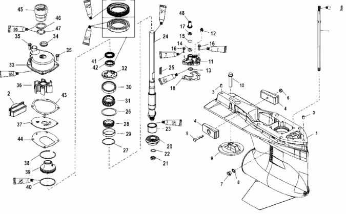
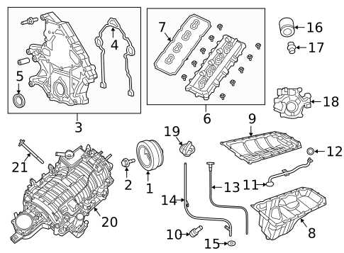
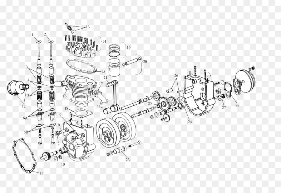
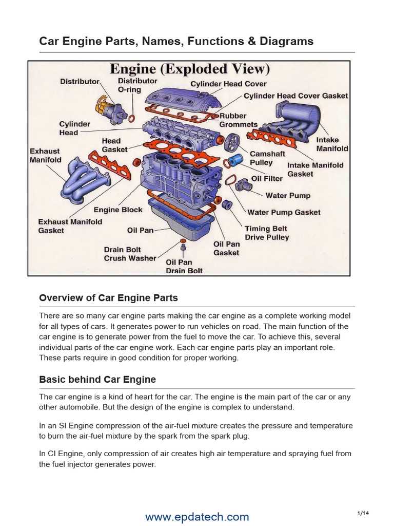
Exploded Views break down components, allowing a clear understanding of how individual pieces fit together. This type is particularly useful during assembly or disassembly, providing clarity on the arrangement of each element.
Flowcharts illustrate processes, guiding users through operational steps and sequences. They are particularly effective in troubleshooting scenarios, helping to pinpoint issues systematically.
In summary, these various visual tools cater to different aspects of machinery understanding, each offering unique insights that ultimately enhance repair and maintenance efficiency.
Key Components in a Motor Diagram
Understanding the essential elements of a mechanical system is crucial for effective operation and maintenance. Each component plays a vital role in the overall functionality, contributing to the efficiency and reliability of the entire assembly.
Essential Elements
Windings are integral for generating magnetic fields, influencing the performance of the entire structure. The stator and rotor collaborate to create motion, showcasing the harmony between stationary and moving parts.
Support Structures
Frameworks and bearings provide necessary stability, ensuring smooth operation while minimizing friction. Proper alignment of these components is key to maximizing longevity and efficiency.
How to Read Motor Parts Diagrams
Understanding the layout of mechanical components is essential for effective maintenance and repair. This knowledge allows enthusiasts and professionals alike to navigate complex systems, ensuring accuracy in identifying each element’s function and interrelationship.
Begin by familiarizing yourself with common symbols and notations used in these representations. Many illustrations follow standard conventions, which can greatly simplify the learning process.
Next, take note of the overall structure. Identify the main assembly and observe how individual elements connect to one another. This will help you grasp the flow of operation and the role of each section.
Lastly, consult accompanying documentation or manuals. These resources often provide valuable insights into the specifics of the components and their intended interactions, allowing for a deeper understanding.
Common Symbols in Motor Diagrams
Understanding the visual language used in technical illustrations is crucial for effective analysis and communication. Symbols serve as a universal code, allowing technicians and engineers to convey complex concepts succinctly. Familiarity with these representations enhances comprehension and facilitates troubleshooting.
| Symbol | Description |
|---|---|
| ⚫ | Indicates a connection point or terminal. |
| Represents a rotational mechanism. | |
| ⚡ | Signifies electrical flow or power source. |
| Denotes a linkage or relationship between components. | |
| ⏹️ | Indicates a stop or halt function. |
Creating Your Own Motor Diagram
Designing a visual representation of mechanical components can be an enriching experience. It allows enthusiasts to better understand the relationships and functions of various elements within a system. Whether for educational purposes or personal projects, crafting such illustrations enhances comprehension and facilitates problem-solving.
Step 1: Begin by gathering all necessary information regarding the components you wish to illustrate. This includes specifications, functions, and interconnections. Research is essential to ensure accuracy.
Step 2: Choose an appropriate medium for your illustration. You can opt for traditional drawing tools or digital software. Each method has its advantages and can impact the clarity of your final product.
Step 3: Draft a layout that logically represents how each element interacts within the system. Focus on clarity and simplicity to ensure the illustration is easily understood by others.
Step 4: Add labels and descriptions to enhance the informational value of your representation. Clearly marked features aid viewers in grasping complex concepts swiftly.
By following these steps, you can create a detailed and informative visual representation that serves as a valuable tool for learning and communication.
Using Diagrams for Troubleshooting
Visual representations play a crucial role in diagnosing issues within complex systems. By providing a clear overview of components and their interconnections, these illustrations help users identify potential failures quickly and efficiently. Understanding the layout can significantly streamline the problem-solving process.
Benefits of Visual Aids
Utilizing visual aids enhances comprehension and retention, making it easier to grasp intricate relationships. It allows for a more systematic approach to identifying anomalies and encourages a thorough investigation of each element.
Common Issues Addressed
| Issue Type | Description |
|---|---|
| Electrical Failures | Identifying shorts or broken connections. |
| Mechanical Wear | Detecting signs of friction or misalignment. |
| Fluid Leaks | Locating areas of potential leakage. |
Motor Parts Diagrams in Education
Visual representations play a crucial role in the educational landscape, particularly in technical disciplines. They facilitate comprehension by breaking down complex systems into understandable segments, allowing learners to grasp intricate mechanisms and their functionalities.
Enhancing Learning Outcomes

Utilizing schematic illustrations can significantly boost learning outcomes. When students engage with these visuals, they develop a clearer understanding of how components interact, leading to a deeper mastery of concepts. Furthermore, these representations can serve as effective tools for problem-solving and analysis.
Applications in Training

In training environments, these illustrations are invaluable. They not only assist in practical applications but also enhance retention of information. By integrating these visuals into curricula, educators can ensure that students are well-equipped with the knowledge necessary for future challenges.
Digital vs. Printed Motor Diagrams
The choice between electronic and traditional illustrations for mechanical components significantly influences the efficiency and convenience of repairs and maintenance. Each format presents its own set of advantages and disadvantages, impacting accessibility, usability, and user experience. Understanding these differences is crucial for professionals and enthusiasts alike.
Advantages of Digital Illustrations
Electronic formats provide numerous benefits, including easy access, the ability to zoom in for detailed views, and interactive features that enhance understanding. Users can often search for specific information quickly, making it a preferred choice for many.
Benefits of Traditional Illustrations
Printed visuals, on the other hand, offer tangible convenience. They are easy to annotate and do not rely on battery life or electronic devices, making them accessible in any environment. For some, the tactile experience of working with a physical document can also enhance focus and retention.
| Feature | Digital Illustrations | Printed Illustrations |
|---|---|---|
| Accessibility | High, requires device | Always available |
| Interactivity | Yes, clickable elements | No |
| Durability | Device-dependent | Physical wear and tear |
| Annotation | Digital tools available | Easy manual notes |
Resources for Finding Diagrams
Accessing visual representations for various components is essential for effective maintenance and repair. Numerous platforms offer extensive collections of these illustrations, enabling users to identify and understand different elements quickly. Whether you are a professional or a hobbyist, leveraging these resources can enhance your knowledge and skillset.
Online Libraries
Many websites serve as vast repositories for illustrations and schematics. These platforms often categorize content by type or manufacturer, making it easier to locate specific visuals. Searching through dedicated sections can yield comprehensive guides for assembly and troubleshooting.
Community Forums

Engaging with online communities can provide valuable insights and shared resources. Members frequently post links to helpful visuals and personal experiences, creating a collaborative environment. Participating in discussions can lead to discovering lesser-known yet crucial references.
Future Trends in Motor Diagrams
The evolution of schematics related to mechanical systems is poised to undergo significant transformation in the coming years. As technology advances, these visual representations will not only become more intricate but will also incorporate innovative features that enhance usability and understanding. The integration of smart technologies and data visualization techniques will redefine how users interact with these essential tools, making them more intuitive and accessible.
Integration of Augmented Reality
One of the most exciting trends is the incorporation of augmented reality (AR) into technical schematics. This technology allows users to visualize components in a three-dimensional space, facilitating a deeper understanding of complex structures. With AR, users can overlay digital information onto the physical environment, offering real-time guidance and enhancing training processes.
Data-Driven Insights
Additionally, the future will see a greater emphasis on data integration within these representations. By leveraging real-time analytics, users will be able to access critical information about system performance, maintenance needs, and operational efficiency. This shift towards a more data-centric approach will empower engineers and technicians to make informed decisions, ultimately leading to enhanced reliability and performance of mechanical systems.