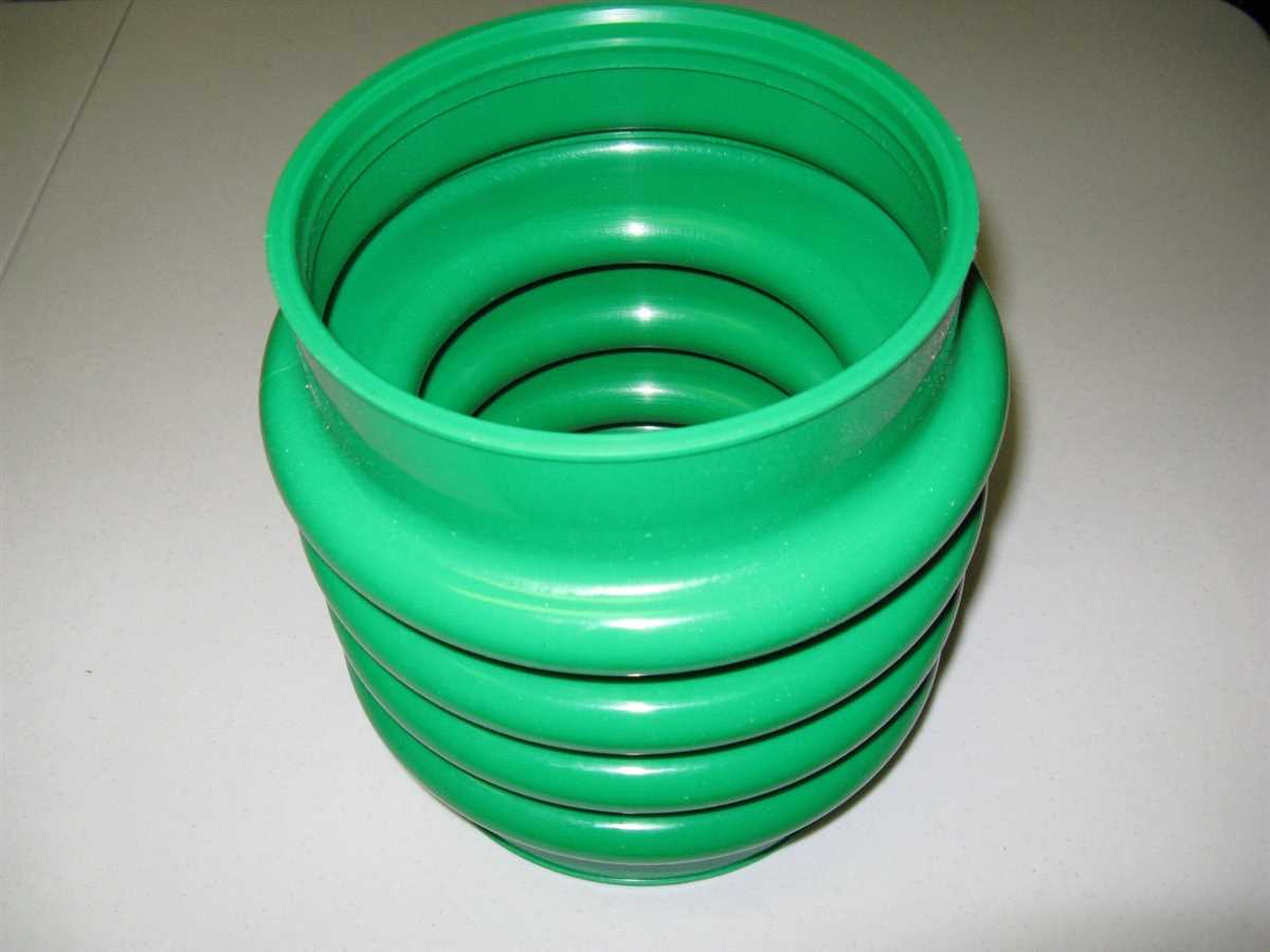
Industrial equipment is designed to withstand harsh environments and deliver reliable performance. To ensure smooth operation, it’s essential to familiarize oneself with the internal structure and the essential elements of such machinery. Knowing how each element interacts within the system can significantly improve maintenance efficiency and prevent potential malfunctions.
When dealing with heavy-duty tools, it’s crucial to understand the arrangement of its internal mechanisms. Whether it’s the engine, various fasteners, or intricate linkages, having a clear mental image of how everything fits together makes it easier to handle repairs or replacements.
In this section, we’ll take a closer look at the intricate setup and key elements that ensure optimal performance. By doing so, you’ll gain a deeper appreciation for the engineering behind this robust piece of equipment and how each piece plays a critical role in its overall function.
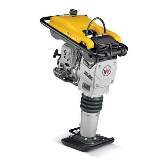
Overview of Wacker BS60Y Components
The core elements of this machine are carefully designed to ensure reliable performance and longevity. Each unit is crafted to work together in harmony, ensuring the equipment runs smoothly even under demanding conditions. In this section, we’ll explore the key elements that contribute to its efficiency and durability.
Main Structural Elements
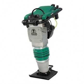
The frame serves as the foundation, providing stability and protection for internal mechanisms. A robust engine powers the entire system, driving all functions with precision. The foot, an essential part of the device, ensures optimal impact force on the surface during operation. These components are engineered for maximum output and durability.
Power and Performance Units
The power system consists of a high-performance engine and a well-calibrated fuel system. This combination ensures steady energy supply and efficient operation. Additionally, the control panel allows the operator to manage the settings with ease, enhancing usability and providing full control over its
Key Features of Wacker BS60Y Rammers
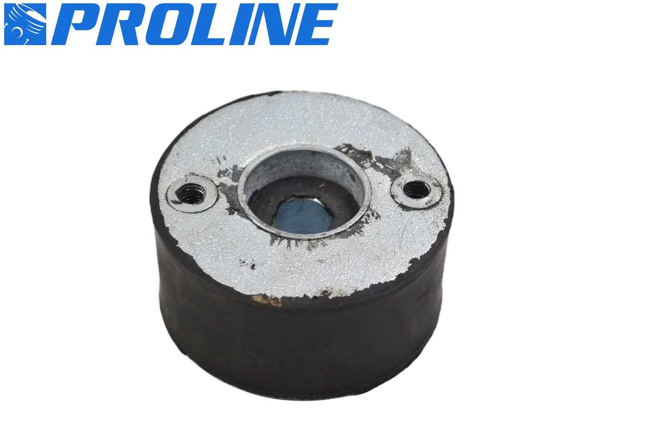
These robust and highly efficient compaction machines are designed to handle various types of terrain and soil conditions. With a focus on durability and performance, they provide powerful compaction while remaining easy to operate. The design ensures stability and reliable operation even in the toughest environments.
Performance and Power
These machines offer an exceptional balance of force and control, making them ideal for compacting different materials. The engine delivers consistent energy, ensuring that each stroke produces optimal compression. This combination of power and precision allows for efficient work, even on uneven ground.
Durability and Maintenance
The materials used in the construction of these machines are built to withstand frequent use and harsh conditions. Regular upkeep is simple, allowing operators to focus on the job without lengthy downtime. The design prioritizes both ease of maintenance and long-term performance.
| Feature | Benefit |
|---|
| Component | Description |
|---|---|
| Clutch Plate | A friction surface that engages and disengages the drive mechanism, allowing for controlled operation. |
| Pressure Plate | Applies pressure to the clutch plate, ensuring firm engagement during operation. |
| Flywheel | A rotating disc that stores kinetic energy and helps maintain engine speed during operation. |
| Drive Shaft | Transfers power from the engine to the driven components, facilitating movement. |
| Bearings | Support the rotating parts, reducing friction and wear for smooth operation. |
Regular inspection and maintenance of the clutch and drive system are vital for ensuring reliability and longevity. Addressing any wear or damage promptly can prevent more significant issues and maintain operational efficiency.
Ignition and Electrical Parts Diagram
This section provides an overview of the ignition and electrical components essential for optimal functionality. Understanding these elements is crucial for effective maintenance and troubleshooting, ensuring that the machine operates efficiently.
The ignition system is responsible for initiating the combustion process, while the electrical components facilitate the proper distribution of power. Each element plays a significant role in the overall performance and reliability of the equipment.
- Ignition Coil: Converts low voltage into high voltage to create a spark.
- Spark Plug: Ignites the fuel-air mixture, ensuring smooth engine operation.
- Flywheel Magnet: Generates electrical current, essential for the ignition system.
- Starter Motor: Initiates engine rotation, allowing for easy starts.
- Battery: Supplies electrical energy to the ignition and electrical systems.
Regular inspections and replacements of these components can significantly enhance performance and extend the lifespan of the equipment. Ensuring that each part is functioning correctly is key to avoiding operational issues.
Foot and Tamper Plate Assembly Details
The foot and tamper plate assembly plays a crucial role in the performance of compaction equipment. This component is designed to deliver powerful vibrations to the ground, ensuring effective soil consolidation. Understanding the intricacies of this assembly is essential for optimal equipment functionality and maintenance.
Foot Assembly: The foot assembly consists of a robust structure that supports the tamper plate. It is engineered to withstand significant stress and impact during operation. This section includes various connecting elements that ensure stability and alignment. Regular inspections are necessary to detect any signs of wear or damage.
Tamper Plate: The tamper plate is the primary surface in contact with the material being compacted. Its design influences the efficiency and depth of compaction. Different materials and finishes can be applied to enhance performance based on specific application requirements. Proper maintenance and cleaning of the tamper plate are vital for prolonging its lifespan and ensuring consistent results.
Understanding these components’ functions and characteristics can significantly improve operational efficiency and extend the service life of the equipment.
Maintenance and Replacement Tips for Key Parts
Regular upkeep and timely replacement of essential components play a crucial role in ensuring optimal performance and longevity of your equipment. By following a few straightforward guidelines, you can effectively manage the health of your machinery and minimize the risk of unexpected breakdowns.
Here are some valuable suggestions for maintaining and replacing critical elements:
- Inspect Regularly: Conduct routine inspections to identify signs of wear or damage. Pay special attention to high-impact areas and components prone to friction.
- Clean Thoroughly: Keep all parts clean and free from debris. Dirt and grime can cause parts to wear prematurely and hinder functionality.
- Lubricate Moving Parts: Apply appropriate lubricants to moving components to reduce friction and enhance efficiency. Regular lubrication can extend the life of various elements.
- Follow Manufacturer Recommendations: Adhere to the maintenance schedule provided by the manufacturer. This schedule typically includes guidelines for inspections, cleaning, and part replacement.
- Use Quality Replacements: When replacing components, opt for high-quality alternatives that match the specifications of the original parts. Quality replacements can significantly impact the performance of your equipment.
By implementing these practices, you can ensure your equipment remains in peak condition, reducing the likelihood of costly repairs and enhancing overall reliability.
