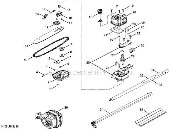
When dealing with the maintenance of small engines, it becomes essential to have a clear understanding of the different elements that make up these machines. Knowing how each piece interacts with the whole can make repairs smoother and more efficient. This is particularly important for those who are handling tools that require precision and proper alignment.
Identifying each element and its connection to the overall system allows for more accurate troubleshooting and replacement of worn-out or damaged sections. With the right visual aid, it’s easier to ensure that everything fits perfectly, avoiding mistakes that could lead to further damage or malfunction.
Whether you are a professional or an enthusiast, understanding the internal structure of your tool will help you in extending its lifespan and maintaining optimal performance. By breaking down the various sections and viewing them in a logical order, one can address any issues with greater confidence and efficiency.
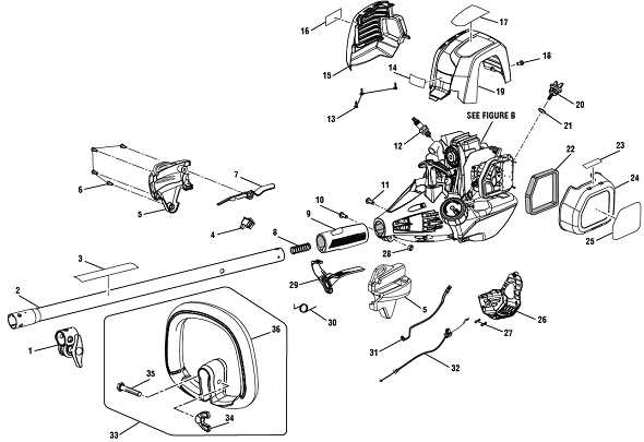
Ryobi SS30 Parts Breakdown Overview
The breakdown of components in this popular model provides a clear understanding of how the equipment is structured. A detailed examination of its internal and external elements reveals the interconnected systems that ensure smooth functionality and durability. Understanding the relationship between each mechanical piece is crucial for maintenance and repairs.
Key Components Structure
This equipment is built with a combination of essential mechanical units that work together to deliver optimal performance. From the engine to the smaller intricate pieces, every component serves a specific function. The layout allows for easy access when servicing is needed, making it convenient for regular upkeep.
Assembly and Maintenance
The design promotes an intuitive approach to both assembly and maintenance, helping users identify individual elements quickly. Proper upkeep extends the lifespan of the machine and ensures that it operates efficiently over time. Each section is designed for quick replacements or adjustments, minimizing downtime during repairs.
Main Components of the Ryobi SS30
The structure of this popular model consists of several key elements that work together to ensure optimal performance. Understanding the fundamental components can help users maintain and repair the unit effectively, ensuring its longevity and reliable operation over time.
Engine Assembly
The core of the unit is the engine, which drives all functions of the machine. This includes several intricate parts that need to be properly maintained, from the crankshaft to the carburetor, each contributing to the smooth running of the system.
Fuel and Ignition Systems
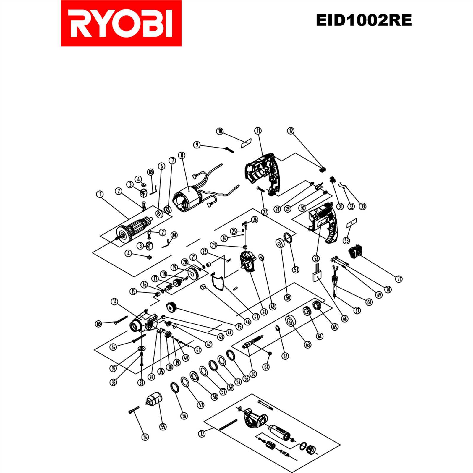
Fuel delivery and ignition are crucial for the model’s operation. The fuel system ensures the correct mix of air and gasoline, while the ignition components provide the necessary spark to start the engine. Regular maintenance of these systems is essential for consistent functionality.
Engine and Fuel System Details
The functionality of the engine relies on a harmonious interaction between its mechanical components and the fuel system. Efficient fuel delivery ensures consistent performance, while the engine’s construction supports durability and power output during operation.
Engine Structure
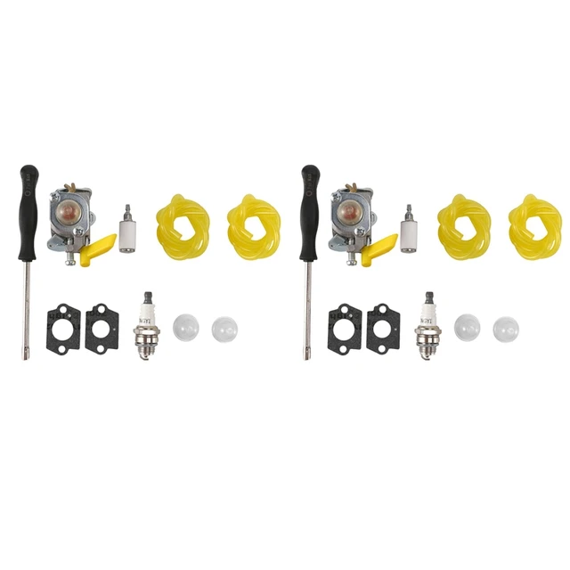
The engine’s core components include the cylinder, piston, crankshaft, and other critical moving parts. These elements work together to convert fuel into mechanical energy. The material and design choices ensure longevity and reliability under varying conditions.
- The cylinder houses the piston and creates the space for combustion.
- The piston moves in response to combustion, driving the crankshaft.
- The crankshaft transforms the piston’s linear motion into rotational force.
Fuel Delivery System
The fuel system is responsible for mixing air and fuel to provide an optimal ratio for combustion. Key components regulate this process to maintain efficient engine performance and prevent fuel waste.
- The carburetor mixes fuel and air before it enters the combustion chamber.
- The fuel tank stores fu
Understanding the Trimmer Shaft Assembly
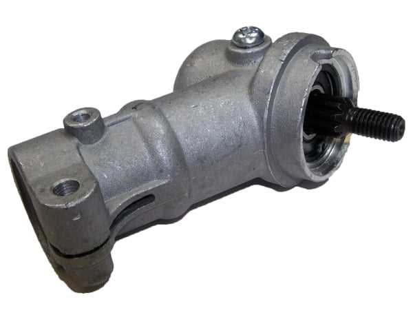
The trimmer shaft assembly is a key component that connects the cutting head to the motor. It ensures the smooth transmission of power from the engine to the cutting mechanism, allowing the tool to function effectively. Proper understanding of its structure and maintenance is essential for ensuring long-term reliability and performance.
Key Components of the Shaft Assembly
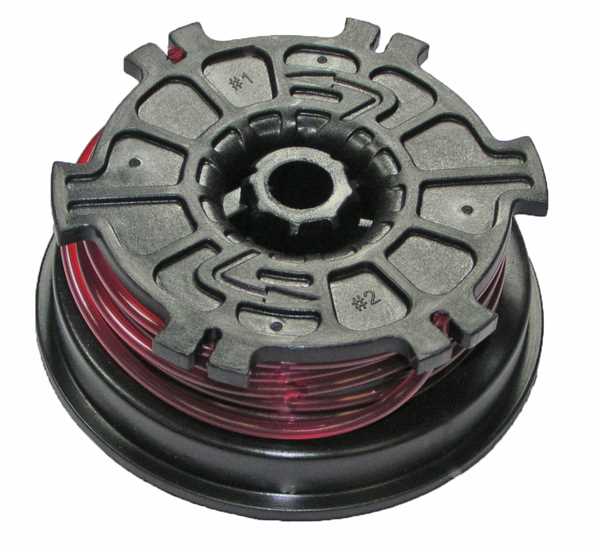
The shaft assembly consists of several integral parts that work together to transfer power. These include the outer tube, drive shaft, and various connectors. Each of these elements plays a distinct role in ensuring the smooth rotation and function of the trimmer head. Regular inspection of these parts can help prevent breakdowns and ensure efficient operation.
How the Shaft Assembly Functions
The drive shaft, housed within the outer tube, spins rapidly when the engine is running. This rotation is transferred through a series of gears or couplings, ultimately reaching the cutting head. The stability of the assembly ensures minimal vibration and allows for precise cutting, making it
Clutch and Drive Mechanism Explained
The clutch and drive mechanism plays a critical role in the operation of many small engines, acting as the bridge between the power source and the tool or machine’s functional components. This system ensures the smooth transfer of energy while allowing controlled engagement and disengagement of the moving parts. By managing torque and speed, the clutch system enhances efficiency and prevents mechanical damage.
In essence, this mechanism allows for power transmission when needed, while also providing a safeguard against overloading or excessive wear. Below is a detailed breakdown of the key components involved:
Component Function Clutch Drum Encases the rotating elements and transfers energy to the drive system. Drive Shaft Connects the power Air Filter Housing and Maintenance
The air filter housing plays a crucial role in the overall efficiency and performance of outdoor power equipment. It serves as a protective enclosure for the air filter, ensuring that only clean air enters the engine, which is vital for optimal combustion. Regular maintenance of this component is essential to prolong the lifespan of the machine and maintain its operational effectiveness.
To begin maintenance, regularly inspect the air filter housing for any signs of dirt or debris accumulation. A clean housing allows for better airflow and engine performance. Removing the air filter periodically is necessary to check for clogs or excessive dirt buildup. If the filter appears dirty, it should be cleaned or replaced as needed.
Furthermore, ensure that the housing is properly sealed to prevent contaminants from entering. Over time, gaskets and seals may wear out, leading to inefficiencies. Regularly replacing these seals can enhance the performance and reliability of the equipment. Ultimately, prioritizing the upkeep of the air filter housing will result in improved engine performance and longevity of the machinery.
Throttle Control and Trigger Function

The throttle control mechanism plays a crucial role in regulating the power output of handheld equipment. It allows users to adjust the engine’s speed, providing precise control over the tool’s performance. Understanding how this component interacts with the trigger is essential for effective operation.
In this context, the trigger serves as the primary interface for the user, enabling them to engage and modulate the throttle with ease. When the trigger is pulled, it activates the throttle, allowing fuel to flow into the engine and increase power. This responsiveness ensures that operators can execute tasks with accuracy, adapting the machine’s speed to suit various applications.
Maintaining the functionality of the throttle control and trigger assembly is vital for optimal performance. Regular inspections and timely replacements of worn parts contribute to reliable operation and enhanced safety. Users should familiarize themselves with these components to ensure effective troubleshooting and maintenance.
Ignition System Parts and Replacement
The ignition system is a critical component in the functioning of outdoor power equipment, ensuring that the engine starts reliably and operates efficiently. Understanding the elements involved in this system and knowing when to replace them can significantly enhance performance and longevity.
Key components of the ignition system include:
- Ignition Coil: This part generates the high voltage required to create a spark in the spark plug.
- Spark Plug: Responsible for igniting the fuel-air mixture in the combustion chamber.
- Flywheel Magnet: Engages with the ignition coil to produce a spark.
- Wiring Harness: Connects all electrical components, facilitating communication and power distribution.
- Kill Switch: Shuts down the engine when activated, ensuring safety during operation.
Regular maintenance and timely replacement of these elements are essential for optimal performance. Here are some signs indicating the need for replacement:
- Difficulty Starting: If the engine struggles to start or fails to ignite, the ignition coil or spark plug may be faulty.
- Engine Misfire: Irregular engine performance can signify issues with the spark plug or ignition timing.
- Electrical Problems: Damaged wires or connectors can lead to a complete failure of the ignition system.
To replace these components, consult the equipment manual for specific guidelines. Ensure to use compatible replacements to maintain performance and reliability.
Handle and Grip Assembly for Comfort
The design of the handle and grip assembly plays a crucial role in ensuring a comfortable user experience during operation. A well-crafted handle allows for a natural grip, reducing fatigue and enhancing control while using the equipment. This section focuses on the elements that contribute to a more ergonomic experience, highlighting the importance of comfort in handling tools effectively.
Components of the Handle Assembly
The handle assembly consists of several key components that work together to provide a secure and comfortable grip. Each part is designed to support the user’s hand, allowing for extended use without discomfort. Below is a breakdown of the essential elements:
Component Description Handle Grip Soft, textured surface that ensures a non-slip hold. Handle Frame Durable structure that supports the grip and connects to the main body. Trigger Assembly Located within the handle, it allows for easy activation of the tool. Padding Additional cushioning that enhances comfort during prolonged use. Benefits of an Ergonomic Design
An ergonomic handle design significantly enhances the overall user experience. By reducing strain on the hands and wrists, it allows users to operate the tool for longer periods without discomfort. The thoughtful arrangement of grip features also aids in precision and control, making it easier to navigate tasks with confidence.
Fuel Line and Carburetor Linkage
This section delves into the critical components responsible for the fuel delivery and control mechanisms within small engine equipment. Understanding these elements is essential for maintaining optimal performance and ensuring smooth operation. The fuel line is vital for transporting gasoline to the carburetor, while the linkage connects the throttle and choke controls, enabling precise regulation of the air-fuel mixture.
Fuel Line Functionality
The fuel line serves as the conduit through which fuel flows from the tank to the carburetor. It is typically constructed from durable materials to withstand the corrosive properties of gasoline. Proper routing and securing of the fuel line are crucial to prevent leaks and ensure consistent fuel delivery. Regular inspection of this component is recommended to identify any signs of wear or damage that may impede functionality.
Carburetor Linkage Mechanics
The linkage system connects the throttle and choke levers to the carburetor, allowing the user to adjust the engine’s performance easily. This mechanism translates user input into mechanical movement, altering the air-fuel mixture for efficient combustion. A well-maintained linkage ensures responsive engine performance and prevents issues such as stalling or rough idling.
Component Description Fuel Line Transports fuel from the tank to the carburetor. Throttle Linkage Connects the throttle control to the carburetor for speed adjustment. Choke Linkage Regulates the air-fuel mixture for starting and warming up the engine. Blade Guard and Cutting Head Structure
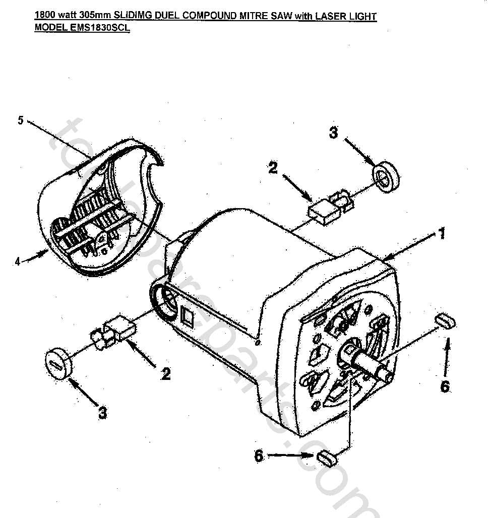
The protective cover and the cutting mechanism are crucial components of any outdoor power equipment, designed to enhance safety and efficiency during operation. The interplay between these elements not only ensures optimal performance but also minimizes the risk of accidents, making them essential for users.
Design and Functionality
The blade guard serves as a protective barrier, shielding the user from potential injuries caused by rotating blades. Its construction typically involves durable materials that withstand wear and tear while offering a clear view of the cutting area. This transparency allows operators to maintain precision without compromising safety.
Cutting Mechanism Configuration
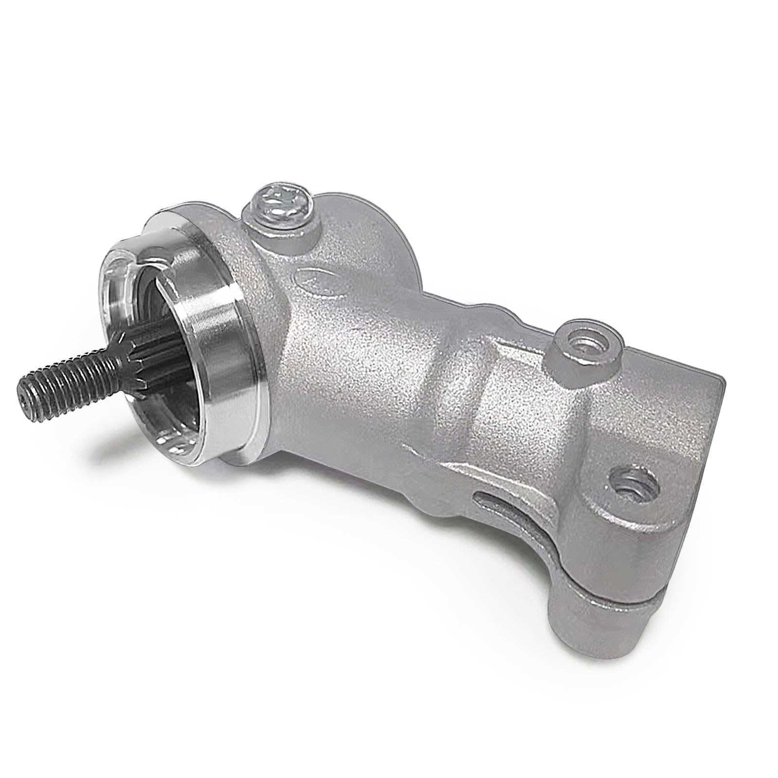
The cutting head is engineered to deliver superior cutting power, often featuring interchangeable blades for various applications. This versatility enables users to tackle different tasks, from trimming grass to clearing tougher vegetation. The structure ensures easy maintenance and replacement, allowing for prolonged use and enhanced productivity.
Proper Lubrication and Seals for Longevity
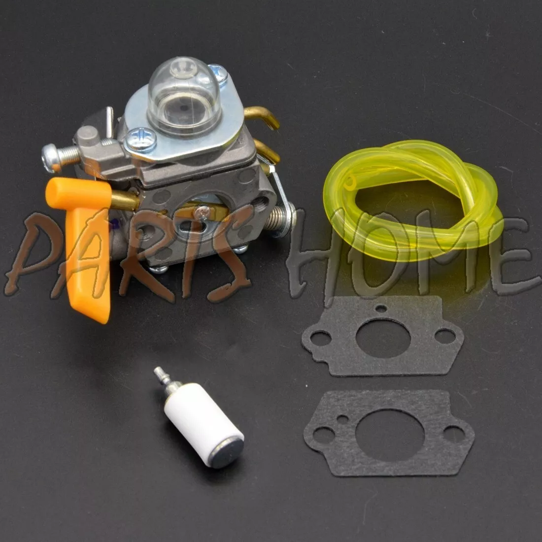
Ensuring the optimal performance and durability of outdoor equipment requires attention to lubrication and sealing components. These elements play a crucial role in reducing friction, preventing wear, and protecting internal mechanisms from contaminants. By maintaining appropriate lubrication levels and utilizing effective sealing materials, users can significantly extend the lifespan of their machinery.
Regular inspection and maintenance of lubricants are vital. Utilizing high-quality grease or oil, tailored to the specific needs of the equipment, can lead to smoother operation and prevent overheating. Additionally, seals must be checked periodically for signs of wear or damage. Effective seals not only prevent leaks but also keep dirt and moisture at bay, which is essential for maintaining functionality.
Lubrication Type Recommended Use Multi-purpose Grease General lubrication of moving parts Oil Use for high-speed components Heavy-Duty Grease For components exposed to extreme conditions Following the manufacturer’s guidelines for lubrication and seal maintenance will ensure equipment operates efficiently and reliably over time. Regular care not only enhances performance but also saves time and money by reducing the need for repairs or replacements.