When working with complex mechanical systems, having a clear understanding of how each individual element functions is essential for efficient troubleshooting and maintenance. Detailed layouts of mechanical systems provide valuable insights into how various elements interact, ensuring smooth operation and longevity. This guide aims to offer an organized overview of important mechanisms and their connections within a larger assembly.
Focusing on the intricate arrangement of mechanical components, we will explore how various sections contribute to overall functionality. Whether you’re looking to enhance your technical skills or simply need guidance in identifying different connections, this resource is designed to assist in breaking down intricate systems into manageable and understandable segments.
By providing a clear overview of the structural and functional layout, this guide offers the foundation needed to effectively handle complex repairs or routine maintenance. With proper understanding, you can ensure optimal performance and extend the lifespan of your equipment.
Overview of Key Components
In this section, we will explore the essential mechanical elements that ensure the functionality and performance of the device. Each component works together to create a reliable system that operates efficiently under various conditions. Understanding these core elements is critical for proper maintenance and troubleshooting.
Engine Assembly
The heart of the system is the motor unit, designed for durability and efficiency. It includes a range of sub-elements that contribute to smooth operation. Regular inspection of this area can prevent significant issues in the future.
- Cylinder block
- Piston and rings
- Crankshaft
Cutting Mechanism
This section is responsible for the main task of the machine. With its precise design and robust materials, the mechanism ensures consistent performance. Proper care of this part guarantees longer operational life.
- Guide bar
Chainsaw Engine Assembly Structure
The internal structure of a chainsaw’s power unit is designed for optimal performance and durability in demanding conditions. This section will explore the main components involved in the assembly, highlighting the intricate connections that enable smooth operation. By understanding the various elements, users can better appreciate how each part contributes to the overall efficiency of the machine.
Main Engine Components
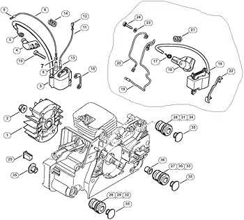
At the heart of the engine are several critical components, including the cylinder, piston, and crankshaft. These elements work in unison to convert fuel into mechanical energy, powering the cutting process. The cylinder houses the piston, which moves up and down, while the crankshaft translates this movement into rotational force. These processes form the core of the engine’s operation.
Ignition and Fuel Systems
The ignition system is responsible for generating the spark that ignites the fuel mixture inside the engine. Alongside this, the fuel system, consisting of a carburetor and intake mechanisms, ensures the proper flow of fuel and air. These systems must be perfectly calibrated to maintain efficient combustion
Guide Bar and Chain Setup
Proper assembly and maintenance of the guide bar and cutting chain are essential for the efficient operation of your equipment. This section will cover the key steps involved in preparing these components, ensuring both optimal performance and safety during use.
- Ensure the correct length and type of the guide bar is selected based on the intended usage and conditions.
- Verify that the chain matches the bar in terms of size and gauge for a precise fit.
- Inspect both the bar and chain for any signs of wear or damage before assembly to prevent malfunctions.
- Begin by positioning the guide bar in its appropriate mount, ensuring it’s secure but not over-tightened.
- Align the chain along the bar, making sure the teeth face the correct cutting direction.
- Adjust the tension by tightening or loosening the adjustment mechanism until the chain has slight slack but does not sag.
Regular checks and adjustments of the chain tension and lubrication are crucial for prolonging the lifespan of the components and ensuring smooth operation. Consistent maintenance also reduces the risk of breakdowns during operation.
Internal Mechanisms of the Carburetor
The internal mechanisms of a carburetor play a critical role in maintaining optimal fuel and air mixture for an engine. Understanding how these components work together allows for efficient performance and maintenance of the machine. The complexity of these parts is designed to provide precise control over the combustion process, ensuring that the engine runs smoothly under various conditions.
Fuel Flow Regulation
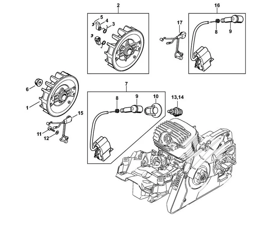
One of the essential functions within the carburetor is to regulate the amount of fuel entering the combustion chamber. This process is achieved through the interaction of the float, needle valve, and fuel jets. Fuel jets control the fuel’s velocity, while the needle valve ensures that the fuel is delivered in proportion to the airflow. When fuel flow is properly balanced, the engine operates efficiently.
Air Mixture Control
Air is drawn into the carburetor through
Detailed View of the Ignition System
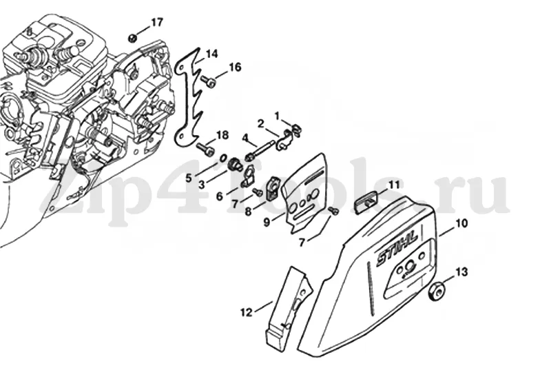
The ignition mechanism is a vital part of any engine, ensuring the proper functioning of the internal combustion process. By converting stored energy into a spark, it ignites the fuel-air mixture, enabling the engine to run smoothly. Understanding the key components of this system will provide insights into its role in maintaining efficiency and performance.
Core Components
The ignition setup typically includes essential elements such as a spark source, wiring connections, and a control unit. These components work together to generate the electrical charge needed for ignition. The energy is stored and released at the precise moment to initiate combustion, ensuring consistent operation.
Common Issues and Maintenance Tips
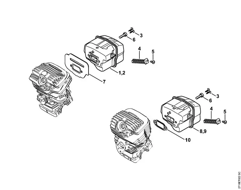
Over time, wear and tear can affect the ignition assembly. Regular checks of wiring and spark sources can prevent malfunctions. Cleaning or replacing worn parts when necessary helps in maintaining optimal performance. Proper upkeep ensures that the entire system continues to function without interruptions.
Fuel and Oil Tank Connections

Understanding the integration of fuel and lubrication reservoirs is crucial for optimal equipment performance. Proper connections ensure efficient flow and prevent leakage, contributing to the longevity of the machinery. This section explores the essential elements involved in connecting these vital components.
Fuel Reservoirs are designed to deliver fuel to the engine, facilitating combustion and power generation. The connections must be secure to avoid spillage and maintain pressure. Regular inspection of the fuel lines for any signs of wear or damage is recommended to ensure reliability.
Lubrication Systems play a critical role in reducing friction between moving parts. The oil tank connection should be checked frequently to confirm that it is free from obstructions and that oil circulates adequately. This helps maintain the efficiency of the machinery and prevents overheating.
Proper maintenance of fuel and oil connections not only enhances performance but also minimizes the risk of operational failures. Implementing routine checks and adhering to manufacturer guidelines can significantly improve the functionality and lifespan of the equipment.
Clutch and Drive Mechanism Layout
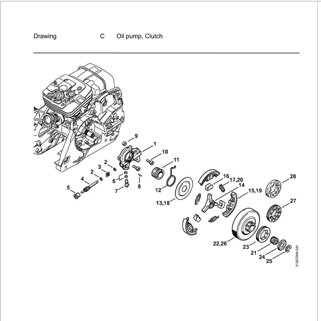
The clutch and drive system play a crucial role in the operation of power tools, ensuring effective power transmission from the engine to the cutting components. This layout involves a series of interconnected parts designed to manage torque and speed, allowing for optimal performance under varying conditions.
At the heart of this mechanism is the centrifugal clutch, which engages and disengages the drive based on the engine speed. As the engine accelerates, the clutch arms extend outward due to centrifugal force, making contact with the drum and transmitting power. Conversely, at lower speeds, the clutch disengages, preventing unnecessary wear on the components and ensuring safety during operation.
The drive system typically consists of a drive shaft, gear assembly, and other vital elements that work in harmony. The drive shaft transfers rotational force from the engine to the cutting head, while the gear assembly may alter the speed and torque characteristics to suit different tasks. Proper alignment and functionality of these components are essential for achieving maximum efficiency and durability.
Regular maintenance and inspection of the clutch and drive system can significantly enhance the longevity and reliability of the equipment. By understanding the layout and operation of these mechanisms, users can ensure optimal performance and reduce the likelihood of mechanical failures during use.
Air Filter Placement and Maintenance
Ensuring optimal performance of your equipment requires careful attention to the air intake system. The positioning and upkeep of the air filtration component are crucial for maintaining engine efficiency and prolonging the life of the machine. Proper care prevents dirt and debris from entering the engine, which can lead to performance issues and damage over time.
When it comes to the placement of the air filter, follow these guidelines:
- Locate the air filter housing, typically situated near the engine.
- Ensure that the filter is seated correctly in its designated compartment.
- Check for any gaps or misalignment that could allow unfiltered air to enter.
Regular maintenance is essential for the air filtration system to function effectively. Here are some recommended practices:
- Inspect the air filter regularly for signs of dirt buildup.
- Clean the filter according to the manufacturer’s instructions, using appropriate cleaning agents.
- Replace the filter periodically, especially if it appears damaged or excessively dirty.
- Monitor engine performance; a drop in power can indicate a clogged air filter.
By following these steps, you can ensure that the air intake system remains clean and functional, contributing to the overall health of your equipment.
Handlebar and Anti-Vibration Design
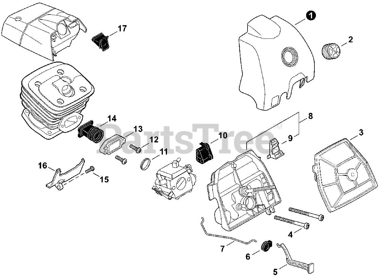
The design of the handlebar and the anti-vibration system is crucial for ensuring user comfort and control during operation. A well-engineered handle provides a secure grip, allowing for precise maneuverability, while the anti-vibration features mitigate the effects of engine vibrations that can cause fatigue over prolonged use.
Comfort and Efficiency are paramount in the design of these components. An ergonomic handlebar shape reduces strain on the user’s hands and wrists, enabling longer periods of work without discomfort. The strategic placement of cushioning materials enhances shock absorption, further enhancing the experience.
Moreover, vibration dampening systems are integrated to minimize the transmission of vibrations from the engine to the operator. These systems typically involve flexible mounts and isolators that absorb shocks, significantly improving handling and reducing the risk of repetitive strain injuries.
Ultimately, a thoughtfully designed handlebar combined with effective vibration control not only enhances performance but also contributes to safer and more enjoyable usage.
Starter Assembly and Operation
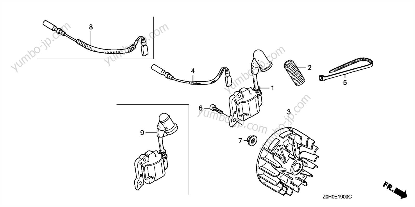
The starter assembly is a crucial component of any engine-driven tool, facilitating the initiation of the power source. Its primary function is to engage the engine’s flywheel and enable the combustion process to begin. Understanding the structure and functionality of this assembly is essential for effective maintenance and troubleshooting.
This assembly typically consists of several key components that work in harmony. Below is a brief overview of the main elements involved:
Component Description Starter Rope A durable cord that, when pulled, rotates the flywheel to start the engine. Recoil Spring Stores energy to retract the starter rope after it has been pulled. Starter Pulley Holds the starter rope and engages with the flywheel when the rope is pulled. Mounting Plate Secures the starter assembly to the engine casing, providing stability during operation. When the operator pulls the starter rope, the recoil spring unwinds, allowing the starter pulley to engage with the flywheel. This interaction generates the necessary torque to initiate the engine. Proper maintenance of the starter assembly is vital to ensure reliable operation, preventing potential failures during usage.
Muffler and Exhaust Configuration
The design of the muffler and exhaust system plays a crucial role in the overall performance and efficiency of power equipment. Proper configuration not only aids in the effective expulsion of combustion gases but also contributes to noise reduction and engine longevity. Understanding the components and their arrangement can enhance maintenance practices and operational effectiveness.
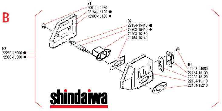
At the core of the exhaust system, the muffler is responsible for minimizing noise while ensuring that the engine operates efficiently. Various designs can affect performance characteristics, including back pressure and exhaust flow. The following table outlines the essential elements involved in the exhaust configuration:
Component Description Muffler Body The main structure that houses internal baffling to reduce noise levels. Exhaust Outlet The opening through which exhaust gases exit, influencing the flow dynamics. Resonator A supplementary device that modifies sound frequencies for improved acoustic performance. Heat Shield A protective cover that helps dissipate heat and safeguard surrounding components. Mounting Brackets Support structures that secure the exhaust system to the engine, ensuring stability during operation. Regular inspection and maintenance of the muffler and exhaust system are vital for optimal operation. Any obstruction or damage can lead to increased emissions and decreased performance. Adopting best practices for upkeep can extend the life of these components and improve overall efficiency.
Throttle Control and Trigger Linkage
The mechanism responsible for regulating engine speed plays a vital role in the operation of various power tools. It serves as the interface between the user and the equipment, allowing for precise adjustments based on task requirements. Understanding this system is crucial for effective management of performance and efficiency.
This assembly consists of several key components that work together to transmit the operator’s commands to the engine. The linkage connects the control lever to the throttle valve, facilitating smooth acceleration and deceleration. Proper maintenance of this system ensures optimal response times and reduces the likelihood of operational issues.
Regular inspection of the linkage for wear and tear is essential. Any signs of fraying or damage can lead to reduced functionality, impacting the overall performance of the equipment. Ensuring all connections are secure and free from debris will enhance reliability during use.