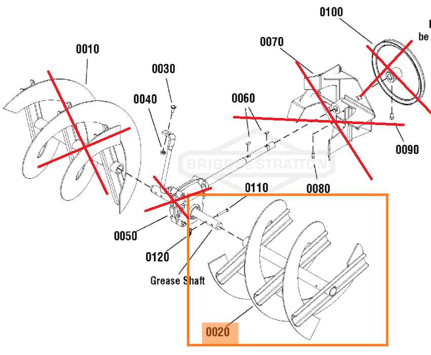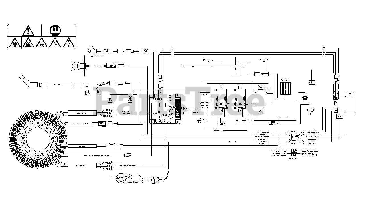
In any mechanical device, understanding the arrangement and connection of essential elements is crucial for both maintenance and repair. This overview focuses on the structure of a high-performance machine, outlining how its various segments interact and function as a cohesive unit. Whether you’re performing regular upkeep or tackling specific repairs, knowing the layout of key elements can simplify the process significantly.
By breaking down each component and its placement, this guide helps you navigate the system more efficiently. We will delve into the major sections, highlighting their purpose and role in the machine’s operation. This approach offers a comprehensive view, ensuring you have the knowledge needed to approach any task with confidence.
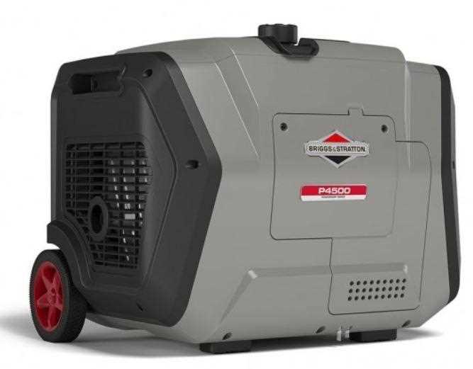
Key Components of the Q6500 Generator
The core elements of this portable power solution are designed to deliver reliability and efficient energy output for various applications. Understanding these main sections allows users to maintain and optimize the unit for long-term performance, while ensuring that it meets the demands of different environments.
Engine and Power Output System
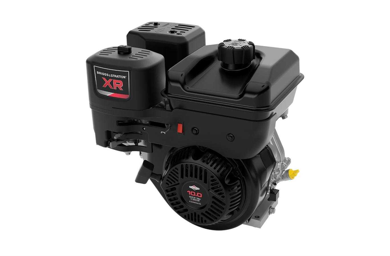
At the heart of the machine lies a robust engine, capable of providing consistent power for extended periods. Its efficient design reduces fuel consumption, ensuring the generator operates smoothly under load. Coupled with an advanced power management system, it guarantees stable electricity output, crucial for sensitive electronics and appliances.
Cooling and Exhaust Mechanism
Effective temperature regulation is critical to prevent overheating during continuous use. The cooling system works in tandem with a streamlined exhaust setup, ensuring the unit remains within safe operating temperatures while minimizing noise and emissions. This combination contributes to quieter performance and prolonged component life.
Exploring the Engine Mechanism
The core of any machine relies on the seamless interaction of its components, working together to generate power and ensure efficient operation. Understanding how each element functions within this framework allows us to appreciate the precision and engineering behind the engine’s performance.
Main Components Overview
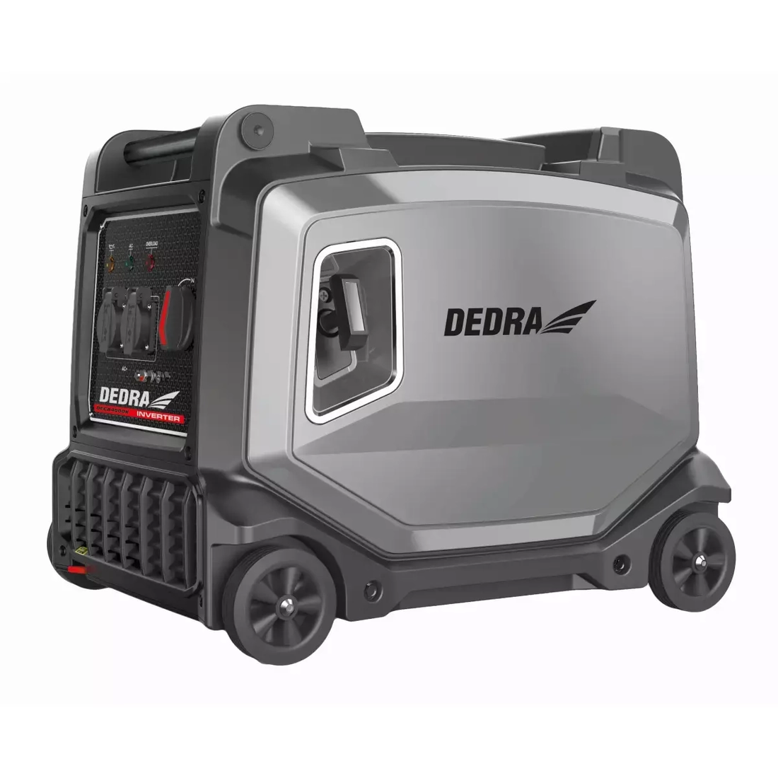
The mechanism at the heart of the system consists of several critical elements, each playing a distinct role in ensuring smooth functionality. Here’s a breakdown of some key components:
- Cylinder Block: The foundational structure that houses the internal parts responsible for combustion.
- Crankshaft: Converts the linear motion of the pistons into rotational energy to power other systems.
- Piston Assembly: Operates within the cylinders to create the necessary pressure for power generation.
- Valves: Regulate the flow of air and fuel into the chamber and control the exhaust of gases.
How It All Works Together
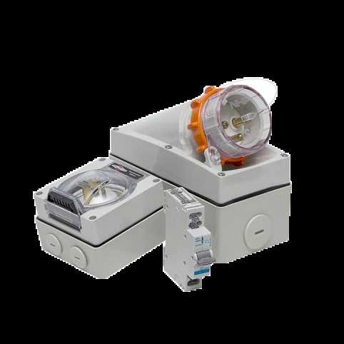
The interaction between these components is what drives the overall system. As fuel ignites, the pistons move within the
Understanding the Fuel System Layout
The fuel system in this power generator is designed to ensure a consistent and efficient delivery of energy. Its components work together to manage the flow and combustion of the fuel, which powers the engine and keeps the system operational. By examining how each part functions, it becomes easier to grasp the overall structure and troubleshoot any issues related to fuel management.
| Component | Function | ||||||||||||||||||||||||||||||||||||||||||||||||||||||||
|---|---|---|---|---|---|---|---|---|---|---|---|---|---|---|---|---|---|---|---|---|---|---|---|---|---|---|---|---|---|---|---|---|---|---|---|---|---|---|---|---|---|---|---|---|---|---|---|---|---|---|---|---|---|---|---|---|---|
| Fuel Tank | Stores the fuel and supplies it to the system through a connected line. | ||||||||||||||||||||||||||||||||||||||||||||||||||||||||
| Fuel Filter | Prevents impurities from entering the engine by filtering the fuel before it reaches the combustion chamber. | ||||||||||||||||||||||||||||||||||||||||||||||||||||||||
| Fuel Line | Transfers fuel from the tank to the other system components, ensuring smooth flow. | ||||||||||||||||||||||||||||||||||||||||||||||||||||||||
| Carburetor | Mixes the fuel with air in the correct ratio for efficient combustion in the engine. | ||||||||||||||||||||||||||||||||||||||||||||||||||||||||
| Component | Description |
|---|---|
| Muffler | A device that reduces sound produced by the engine during exhaust. |
| Heat Shield | Protects surrounding parts from the intense heat produced by the exhaust gases. |
| Exhaust Pipe | Directs the exhaust gases away from the engine to the outside environment. |
| Gaskets | Seal the connections between various components to prevent leaks. |
Cooling System: Essential Parts
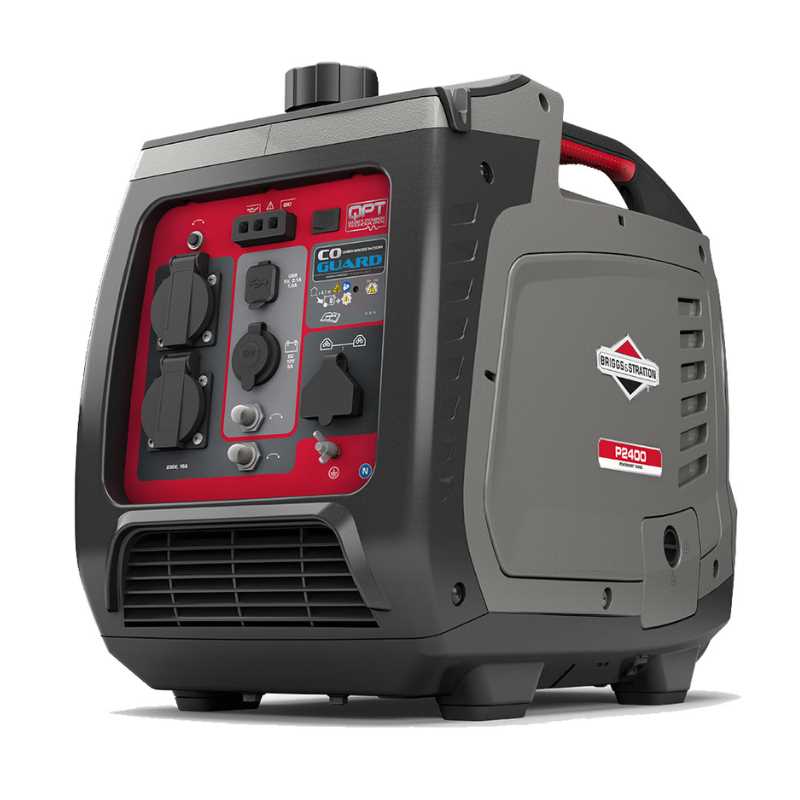
The cooling mechanism is vital for maintaining optimal temperatures, ensuring long-lasting performance and preventing overheating. This section outlines the key elements involved in the system, helping maintain a balanced environment during operation.
Main Components
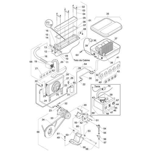
- Fan Assembly: A critical component that helps circulate air, reducing excess heat buildup around the engine.
- Heat Exchanger: This part dissipates warmth by transferring it to the surrounding air, ensuring the system remains efficient.
- Protective Housing: Shields the cooling components from external debris, ensuring they remain effective for longer periods.
Supporting Elements
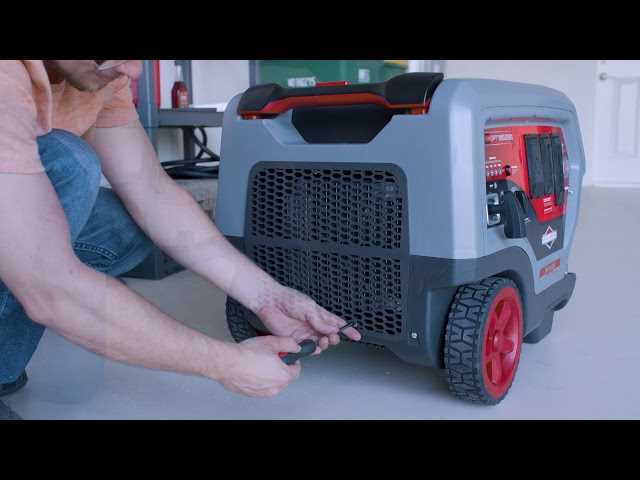
- Air Ducts: Channels designed to direct airflow, improving the overall efficiency of the cooling process.
- Control Sensors: Devices that monitor temperature levels, activating or adjusting the cooling system as needed to prevent overheating.
- Mounting Brackets: Secure the cooling units in place, ensuring stability during use.
Examining the Power Output Section
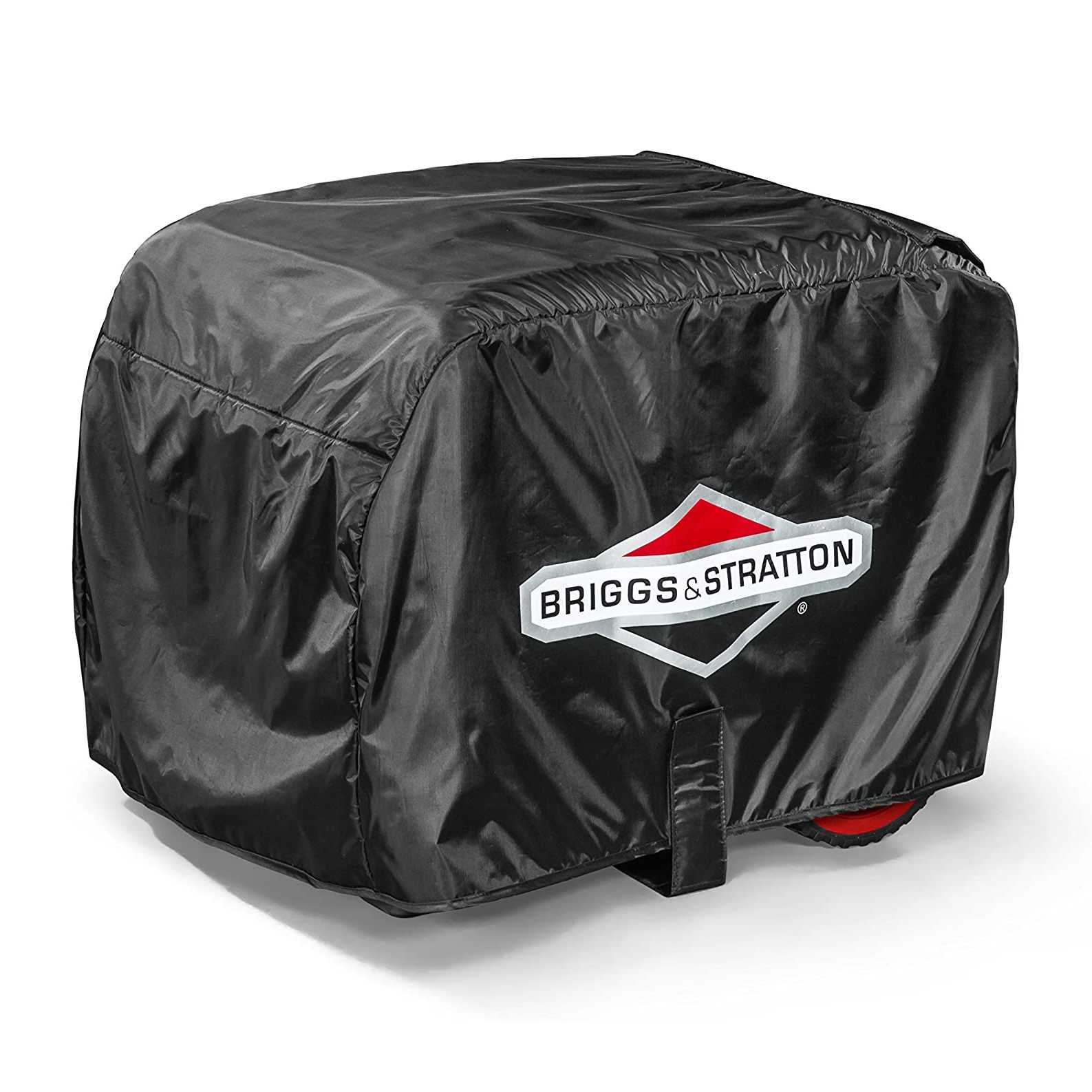
This segment focuses on the essential components responsible for generating and managing electrical energy within the equipment. Understanding the layout and functionality of these elements is crucial for ensuring optimal performance and reliability. Each part plays a significant role in converting mechanical energy into usable electrical power.
| Component | Description |
|---|---|
| Generator | This unit is responsible for converting mechanical energy into electrical energy, ensuring the required output for various applications. |
| Voltage Regulator | This component maintains a consistent voltage level, protecting connected devices from fluctuations that could cause damage. |
| Control Module | This system oversees the overall operation, providing essential diagnostics and adjustments to maintain optimal performance. |
| Wiring Harness | A network of wires that connects all the components, allowing efficient power distribution and communication between parts. |
Starting System Components
The starting mechanism of an engine is vital for its operation, ensuring that the power unit can be activated smoothly and efficiently. This system encompasses various elements that work in harmony to initiate the engine’s performance, each playing a critical role in the process.
| Component | Description |
|---|---|
| Starter Motor | A device that converts electrical energy into mechanical energy to turn the engine over. |
| Battery | Provides the necessary electrical power to the starter motor and other electronic components. |
| Ignition Switch | Controls the electrical flow from the battery to the starter motor, allowing the user to start the engine. |
| Starter Relay | Acts as a switch to engage the starter motor when the ignition switch is turned on. |
| Flywheel | A rotating component that stores kinetic energy and helps in the engine’s initial rotation. |
| Solenoid | Electromagnetic device that pushes the starter gear into engagement with the flywheel. |
Detailed View of the Control Panel
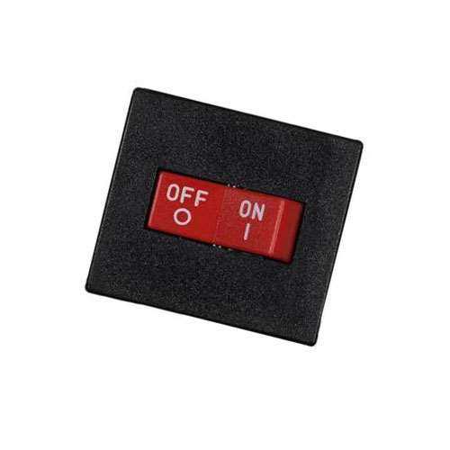
The control panel serves as the central hub for managing various functions of the equipment, allowing users to easily monitor and adjust settings. Understanding the components and their layout is crucial for optimal operation and maintenance.
This section will delve into the specific elements present on the control interface, providing a comprehensive overview of their roles and functionalities. Familiarizing yourself with these components enhances user experience and promotes efficient management of the unit.
| Component | Description |
|---|---|
| Power Switch | Used to turn the unit on and off, ensuring safety and energy conservation. |
| Voltage Selector | Allows the user to choose between different output levels to match the requirements of connected devices. |
| Run Indicator Light | Illuminates when the unit is operational, providing a clear visual cue for the user. |
| Battery Level Gauge | Displays the current charge status, helping users manage power supply effectively. |
| Control Knob | Facilitates fine-tuning of various settings, allowing for precise adjustments. |
Air Filtration System Overview
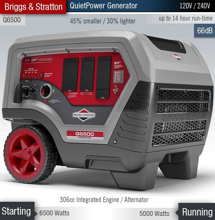
The air filtration mechanism plays a crucial role in maintaining the efficiency and longevity of an engine. It is designed to prevent contaminants and debris from entering the internal components, ensuring optimal performance. Understanding the functionality of this system is essential for proper maintenance and operation.
Key components of an effective air filtration system include:
- Air Filter: The primary element that captures dust, dirt, and other particles.
- Filter Housing: A protective casing that houses the filter, ensuring a secure fit and proper airflow.
- Pre-Cleaner: An optional component that provides an additional layer of defense against larger debris.
- Seals and Gaskets: Essential for preventing unfiltered air from bypassing the filter.
Regular inspection and maintenance of the air filtration system are vital. Neglecting this aspect can lead to reduced engine efficiency, increased fuel consumption, and potential damage over time. Follow these guidelines for optimal upkeep:
- Check the air filter regularly for dirt and debris.
- Replace the filter as recommended by the manufacturer.
- Inspect the housing and seals for any signs of wear or damage.
- Clean the pre-cleaner if applicable.
By prioritizing the maintenance of the air filtration system, users can ensure the engine operates smoothly and effectively.
Maintenance Tips for Electrical Parts
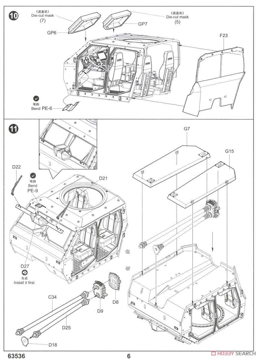
Ensuring the longevity and reliability of electronic components is crucial for optimal performance. Regular upkeep not only enhances functionality but also minimizes the risk of unexpected failures. By following a few essential guidelines, you can keep your electrical elements in top condition and extend their service life.
Regular Inspection
Conducting routine examinations of all electrical components is vital. Look for any signs of wear, damage, or corrosion. Pay special attention to connections and terminals, as these areas are prone to build-up and degradation. Identifying potential issues early can save time and resources in the long run.
Cleaning Procedures

Keeping electrical components clean is essential for their efficiency. Use a soft brush or a cloth to remove dirt and dust from surfaces. For stubborn residue, a mild cleaning solution may be applied, but ensure that it does not harm any sensitive parts. Maintaining cleanliness helps to prevent overheating and ensures optimal operation.
Common Replacement Parts Guide
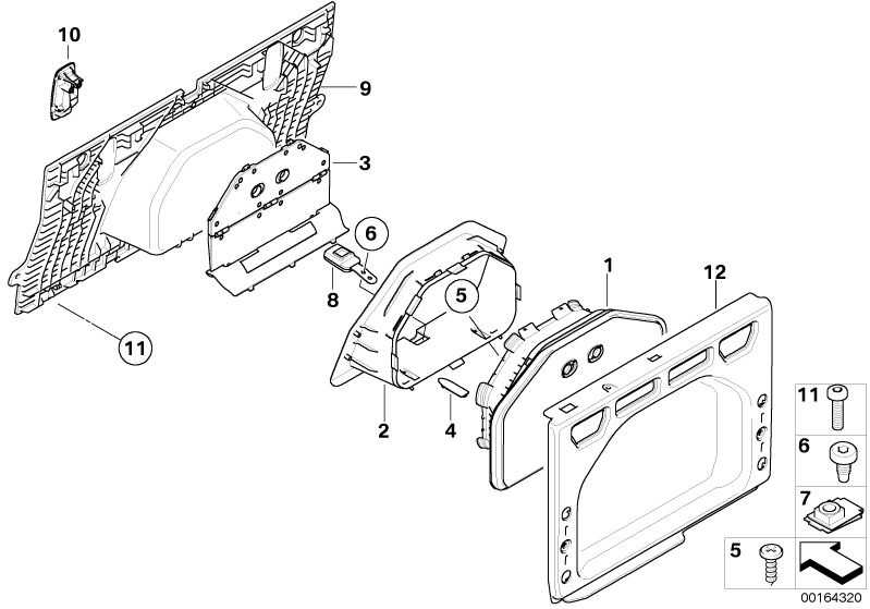
Maintaining outdoor power equipment is essential for optimal performance and longevity. Understanding the frequently needed components can help ensure your machinery runs smoothly. This guide highlights some of the most commonly replaced items that may require attention over time.
Essential Components
Key elements that often need replacement include the fuel filter, which helps to maintain clean fuel flow, and the air filter, crucial for ensuring proper airflow to the engine. Regularly inspecting and changing these components can significantly enhance the efficiency of your equipment.
Additional Considerations
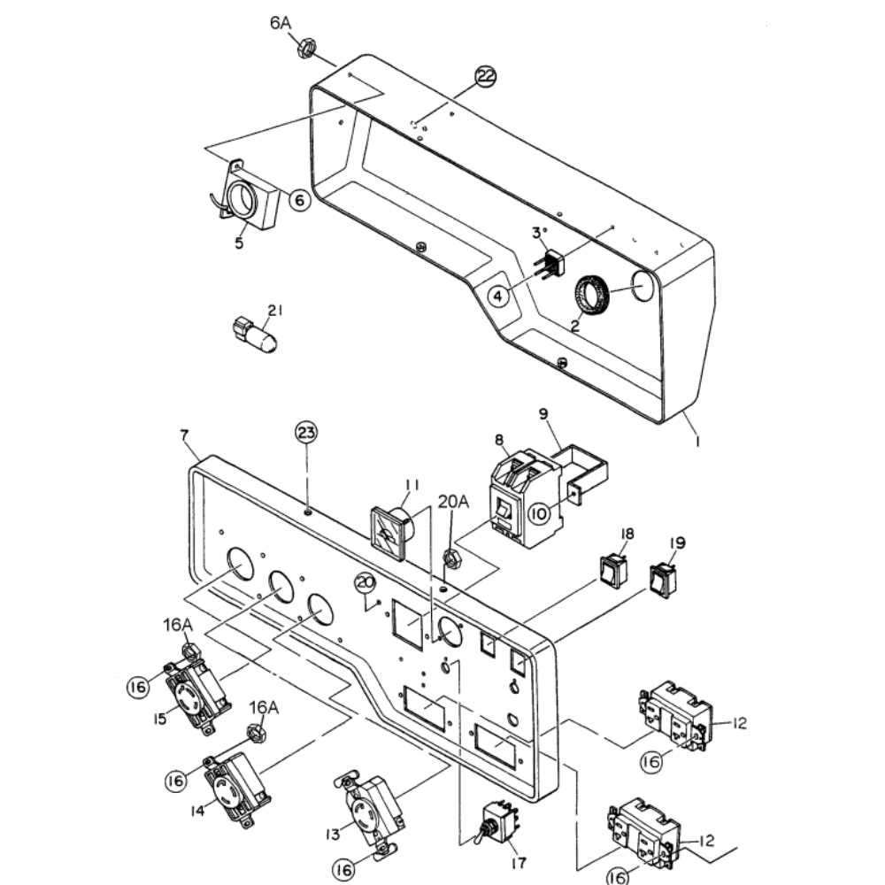
Other notable items include the spark plug, responsible for ignition, and the battery, which powers the unit. Ensuring these components are in good condition can prevent unexpected breakdowns and improve overall functionality. Staying proactive with these replacements will contribute to a more reliable and effective machine.
Safety Features and Protection Systems
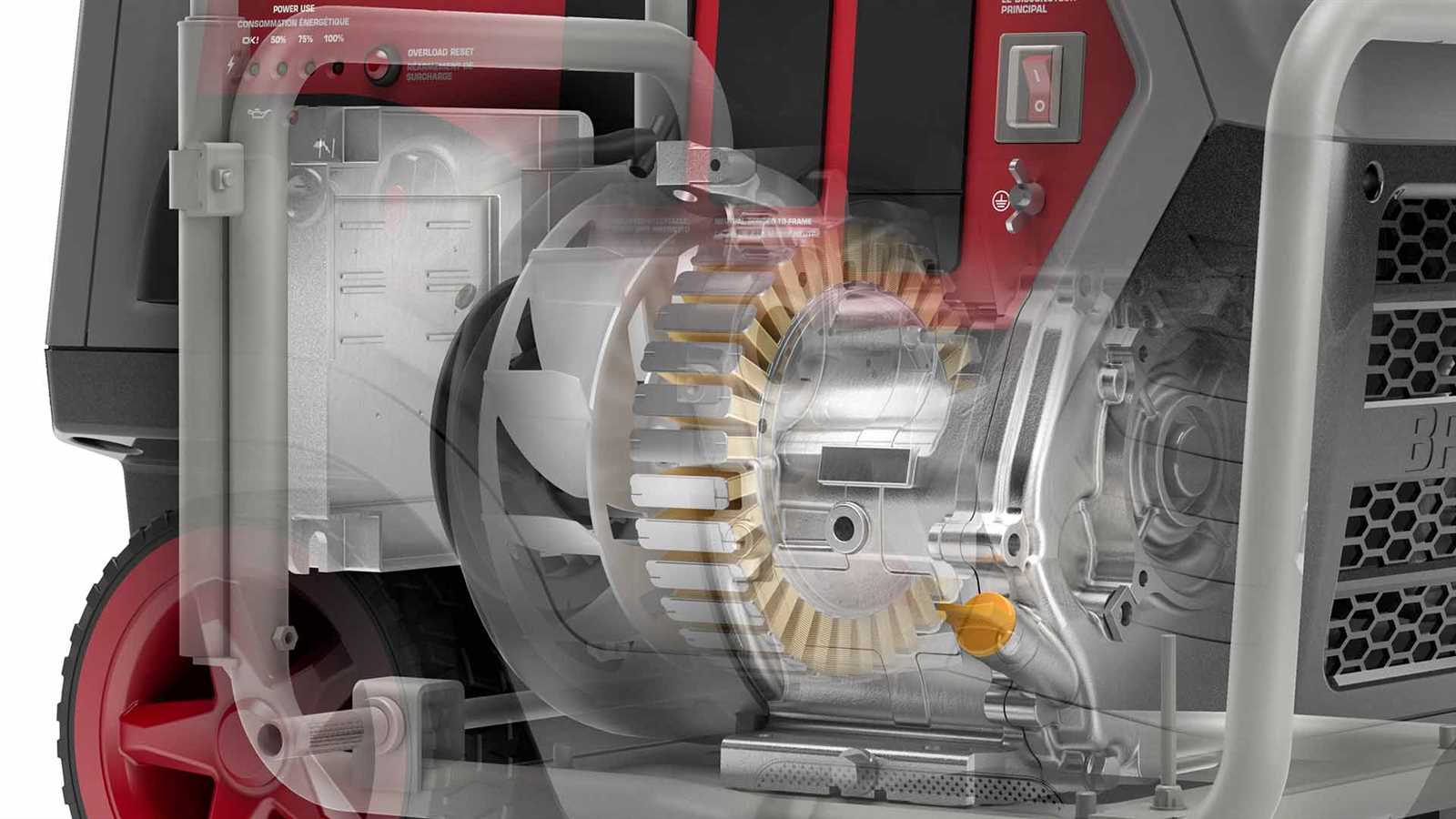
Modern engines are designed with various mechanisms to ensure safe operation and enhance user protection. These features are crucial for preventing accidents and extending the lifespan of the equipment. Understanding these components is essential for anyone utilizing such machinery.
The following table outlines the key safety mechanisms commonly integrated into engine designs, along with their functions:
| Feature | Description |
|---|---|
| Low Oil Shutdown | Automatically turns off the engine when oil levels drop below a safe threshold to prevent damage. |
| Overload Protection | Monitors engine load and prevents operation beyond specified limits, reducing the risk of overheating. |
| Emergency Stop Switch | Allows for immediate shutdown of the engine in case of an emergency, ensuring user safety. |
| Fuel Cut-off Valve | Stops fuel flow to the engine when not in use, minimizing the risk of leaks or fires. |
| Vibration Isolation | Reduces vibrations during operation, enhancing comfort and preventing mechanical failure. |
Incorporating these safety features not only protects the user but also promotes the reliability and efficiency of the machinery, making it a smart choice for various applications.
