In the realm of energy management, understanding the various elements involved in power distribution systems is crucial. These components work together to ensure a seamless transfer of electricity, providing reliability and safety in both residential and commercial applications. This section will delve into the essential aspects of these systems, shedding light on their functionality and significance.
Each component plays a vital role in the overall operation, contributing to the efficiency and effectiveness of the system. From protective mechanisms to control units, the intricate design of these elements allows for optimal performance. By examining these key features, users can gain insights into how to enhance their energy infrastructure, ensuring it meets their specific needs.
Furthermore, understanding the layout and interaction of these elements can aid in troubleshooting and maintenance. A comprehensive grasp of the system’s structure empowers users to identify potential issues and implement solutions promptly. This knowledge is invaluable for anyone looking to optimize their power management setup.
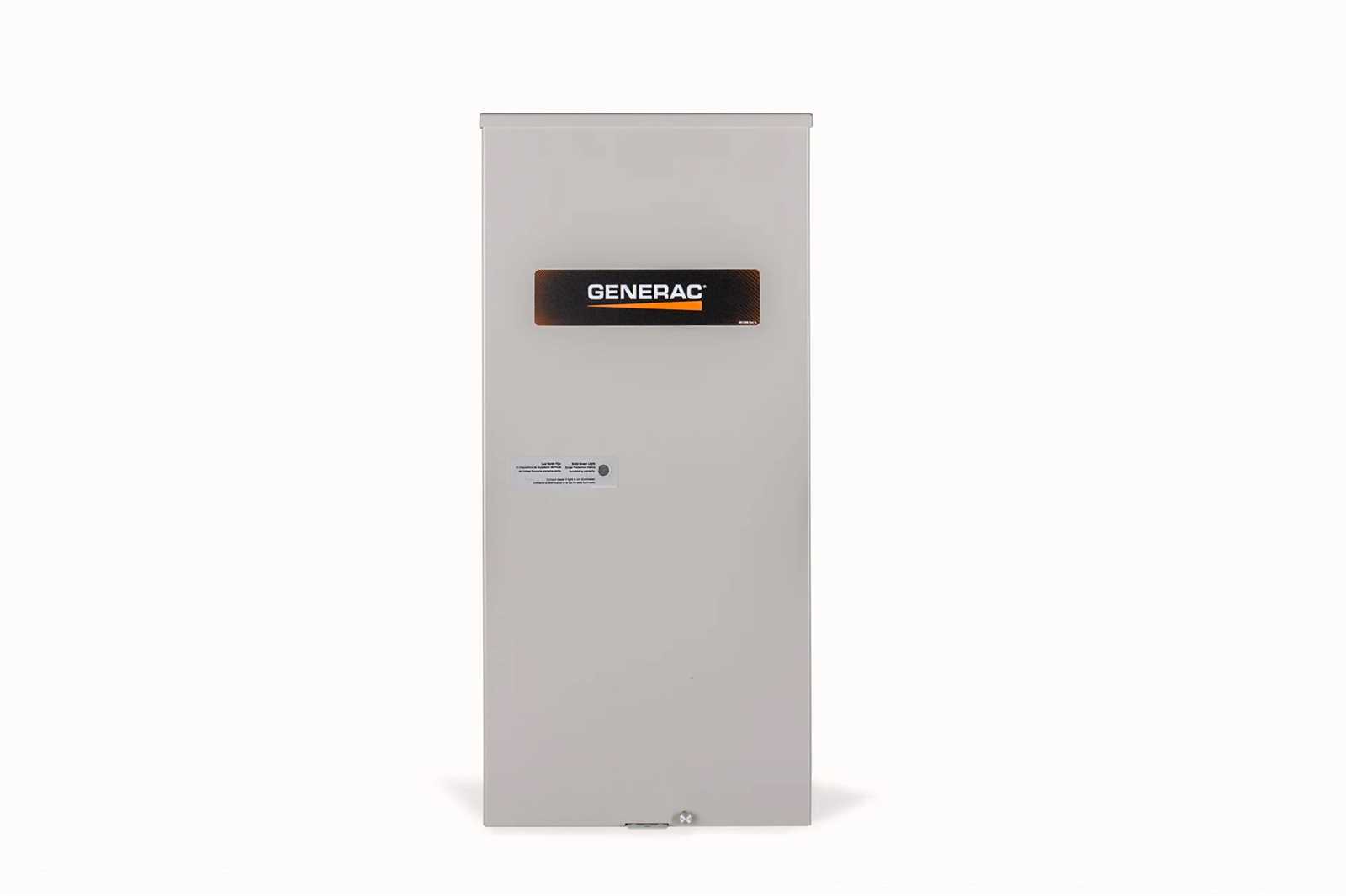
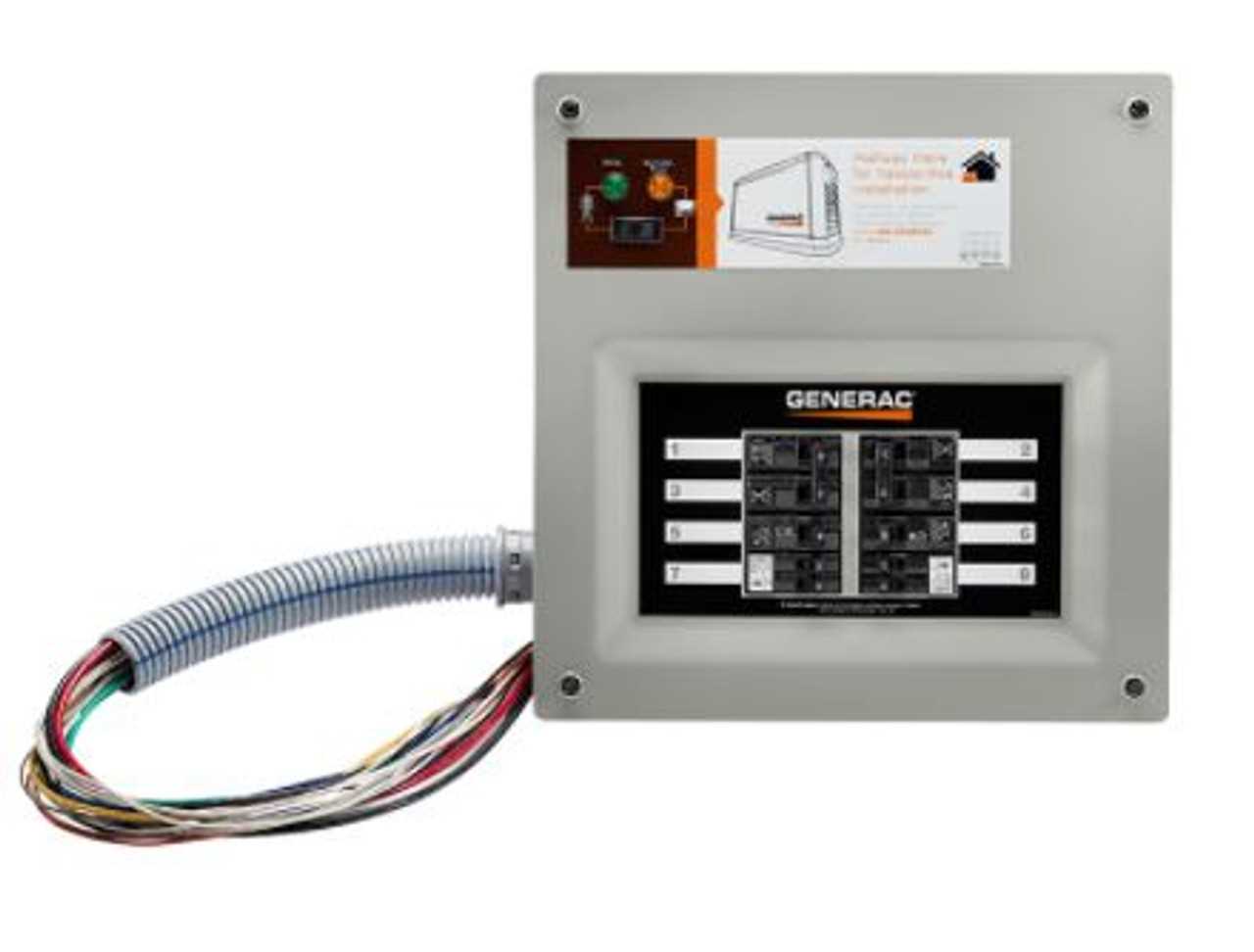
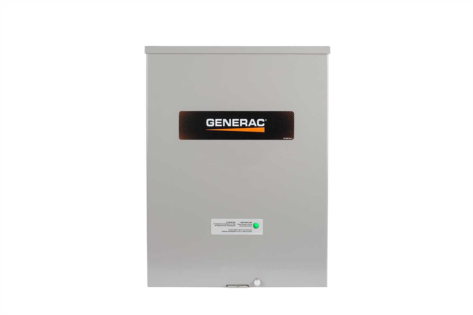
Generac 200 Amp Transfer Switch Overview
This section provides an insight into a crucial component used in home and commercial power systems. It is designed to seamlessly manage the connection between an external power source and the main electrical system, ensuring a smooth transition during power outages. Understanding its functionalities and configurations is essential for effective power management.
Key Features:
- Automatic operation for hassle-free energy supply
- Robust design for long-lasting performance
- Multiple circuit compatibility for versatile applications
Importance: Having a reliable system in place enhances safety and efficiency during emergencies. Users can maintain essential appliances and systems without interruption, ensuring comfort and security when it is most needed.
Conclusion: A well-designed unit significantly contributes to energy reliability and safety, making it an invaluable asset for any property.
Key Components of the Switch

The operation of an electrical control system relies on several essential elements that work together to ensure reliable performance and safety. Understanding these components is crucial for effective maintenance and troubleshooting.
| Component | Description |
|---|---|
| Control Panel | This interface allows users to manage and monitor the system’s functions, providing essential information and control options. |
| Relay | A crucial device that opens or closes circuits based on the electrical signals received, ensuring the system operates correctly. |
| Fuse | This safety device protects the circuit from overloads by breaking the connection when excessive current flows. |
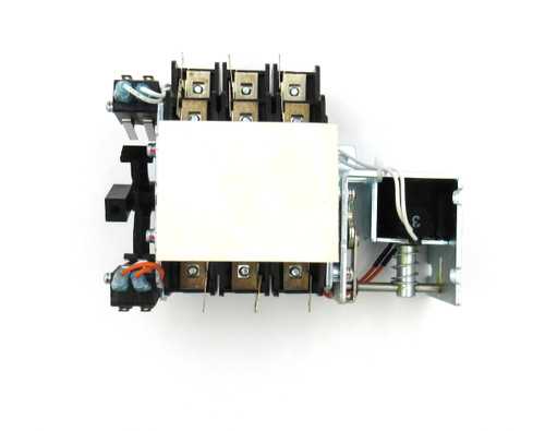
| Transfer Mechanism | This assembly enables the seamless transition of power sources, ensuring uninterrupted operation during outages. |
| Enclosure | A protective housing that safeguards internal components from environmental factors while allowing easy access for maintenance. |
Understanding Transfer Switch Functions
In the context of electrical systems, a device designed to seamlessly connect a primary power source with a backup supply plays a crucial role. This mechanism ensures a stable power supply during outages, allowing essential appliances to operate without interruption. By automatically or manually directing the flow of electricity, it enhances the reliability of power delivery in residential and commercial settings.
These mechanisms are vital for maintaining operational continuity, particularly in critical applications. They offer various functions, such as load management and protection against overloads. Understanding their capabilities can help users maximize efficiency and safety in their electrical systems.
| Function | Description |
|---|---|
| Automatic Switching | Enables the device to detect power loss and switch to a backup source automatically. |
| Manual Control | Allows users to initiate the switch to the backup source manually when needed. |
| Load Balancing | Distributes power evenly across connected devices to prevent overloads. |
| Safety Features | Includes protection against back-feeding and short circuits to enhance user safety. |
Installation Requirements for Generac Switch
When considering the setup of an automatic backup system, it is essential to ensure that all installation prerequisites are met for optimal functionality and safety. Proper planning and understanding of the necessary components and configurations are crucial in creating a reliable power management solution.
Site Preparation
Before installation, assess the location where the backup unit will be placed. Ensure that the area is clear of any obstructions and is suitable for housing electrical equipment. The site should have adequate ventilation and be sheltered from extreme weather conditions to prevent any damage to the system.
Electrical Connections
It is vital to follow all local electrical codes when making connections. Ensure that the circuit breaker panel is accessible and that the necessary wiring meets the specifications for safe operation. Consulting with a qualified electrician can provide guidance on compliance with regulations and optimal wiring techniques.
Maintenance Tips for Longevity

Ensuring the durability and efficiency of your electrical system is crucial for optimal performance and safety. Regular upkeep can prevent issues, extend the lifespan of components, and enhance overall reliability. By implementing a few simple practices, you can maintain your setup effectively.
Routine Inspections
Conducting regular assessments of your equipment is essential. Check for any signs of wear or damage, including loose connections, rust, or corrosion. Keeping an eye on these details can help you identify potential problems before they escalate.
Keep It Clean
Maintaining a clean environment around your installation is vital. Dust and debris can accumulate and affect functionality. Ensure that vents and access points are free of obstructions, allowing for proper airflow and cooling. Regular cleaning not only improves efficiency but also helps prevent overheating.
Remember: consistent attention to maintenance practices can significantly improve the lifespan of your electrical components, ensuring that they operate smoothly when you need them most.
Common Issues and Troubleshooting
In any electrical system, it is essential to be aware of potential problems that may arise and how to address them effectively. Understanding common faults can save time and enhance safety during operation. This section outlines prevalent issues and offers practical solutions for resolving them.
Intermittent Power Supply: One of the frequent challenges encountered is an inconsistent power supply. This issue may stem from loose connections, faulty wiring, or component failure. Inspecting all connections and ensuring they are secure can often rectify this problem.
No Power Output: If the system is not producing any power, it could be due to a blown fuse or a tripped breaker. Check the fuses and reset any breakers to restore functionality. Additionally, ensure that the source of energy is operational and properly connected.
Overheating Components: Components may overheat due to excessive load or poor ventilation. It’s important to monitor the temperature of the system and ensure that it is within safe operating limits. Reducing the load or improving airflow around the equipment can help alleviate overheating.
Frequent Cycling: If the system frequently turns on and off, it may indicate an issue with the control mechanism. Investigate the control settings and consult the user manual for proper configurations. If the problem persists, it may require professional assessment.
Noise and Vibration: Unusual sounds or vibrations can signify mechanical issues. Ensure that all components are securely mounted and that there are no loose parts. Lubricating moving components may also reduce noise and improve performance.
Wiring Schematics Explained
Understanding the intricacies of electrical connections is crucial for ensuring safe and efficient operation. This section delves into the essential components of wiring diagrams, emphasizing their significance in illustrating the flow of electricity and the relationships between different elements in a system.
Components Overview
Wiring schematics typically consist of symbols that represent various electrical components, such as switches, circuits, and power sources. These symbols are standardized to facilitate comprehension and communication among technicians and engineers. By familiarizing oneself with these symbols, one can effectively interpret how a system operates.
Functionality of Connections
Each line in a wiring diagram signifies a connection between components, indicating the pathway through which electrical current travels. Solid lines usually represent conductive paths, while dashed lines may indicate control signals or alternative routes. Understanding these connections is vital for troubleshooting and optimizing system performance.
Importance in Maintenance
Wiring schematics serve as a valuable reference during maintenance and repair tasks. Technicians can quickly identify potential issues, locate components, and understand the interdependencies within the system. This knowledge is instrumental in ensuring that systems remain operational and safe over time.
Conclusion
In summary, grasping the principles behind wiring schematics is fundamental for anyone working with electrical systems. A well-documented diagram not only enhances understanding but also aids in effective troubleshooting and maintenance.
Compatibility with Generac Generators
Understanding the compatibility between various power management systems and generator models is crucial for ensuring optimal performance and safety. This section highlights the essential considerations for connecting different generator types with power control units.
Key Considerations
- Voltage Requirements: Ensure the voltage specifications of the generator match the power control system to prevent malfunctions.
- Wattage Capacity: The generator’s wattage output should align with the requirements of the connected devices.
- Connection Types: Verify that the connection methods are compatible, whether it be via plugs, terminals, or other interfaces.
- Safety Features: Look for built-in safety mechanisms in both the generator and power management system to protect against overloads and short circuits.
Recommended Models
When selecting a generator for use with a power control unit, consider models that are known for their reliability and efficiency. Some widely recommended options include:
- Model A: Known for its high output and efficiency.
- Model B: Offers excellent portability and ease of use.
- Model C: Features advanced safety technologies and user-friendly interfaces.
Safety Features of the Transfer Switch
Ensuring the protection of both users and equipment is crucial when utilizing any electrical system. Various safety mechanisms are integrated into these devices to prevent hazards and promote a secure environment during operation. Understanding these features can significantly enhance safety and reliability.
Key Safety Mechanisms
- Overload Protection: This feature helps to prevent damage caused by excessive current. It automatically disconnects the power supply when the load exceeds safe limits.
- Ground Fault Interruption: This mechanism detects ground faults and swiftly cuts off power, protecting against potential electric shocks.
- Weatherproof Enclosure: A robust exterior shield is designed to protect the components from environmental factors, ensuring safe operation outdoors.
User-Friendly Indicators
- LED Status Lights: These lights provide clear visual feedback about the operational status, helping users identify whether the system is functioning correctly.
- Manual Override: This function allows users to manually operate the device in case of an automatic failure, ensuring continued control over the power supply.
Incorporating these safety features not only protects equipment but also enhances user confidence, making electrical systems safer and more efficient.
Parts Identification and Location Guide
This section serves as a comprehensive reference for recognizing and locating essential components within the system. Understanding the arrangement and function of each element is crucial for efficient operation and maintenance.
Key components and their typical locations include:
- Main Circuit Breaker: Usually situated near the main panel, this device protects the system from overloads.
- Control Panel: Typically located on the front of the unit, it provides user access to various settings and indicators.
- Power Inputs: Found at the rear, these connections facilitate incoming electrical supply.
- Output Terminals: Positioned adjacent to the inputs, these are responsible for distributing power to designated circuits.
- Emergency Shutoff: Located prominently for quick access, this feature allows immediate disconnection in case of emergencies.
Identifying these elements can enhance troubleshooting efforts and ensure that the equipment operates smoothly.
For a detailed examination, refer to the manual that outlines the specifics of each component, including wiring and operational procedures.
Benefits of Using a Transfer Switch
Utilizing a power management device offers numerous advantages for homeowners and businesses alike. It facilitates the seamless transition between different power sources, ensuring that essential systems remain operational during outages. This capability enhances overall reliability and efficiency in power distribution.
Enhanced Safety: Employing such a device significantly reduces the risk of electrical hazards. It prevents backfeeding into the grid, which can endanger utility workers and damage equipment. By safely isolating the power sources, users can operate their generators without fear of creating dangerous situations.
Convenience and Ease of Use: A power management solution simplifies the process of switching between utility and alternative power sources. With a straightforward setup, users can quickly restore power to critical appliances and systems, making it an invaluable asset during emergencies.
Increased Property Value: Installing this device can enhance the overall value of a property. Prospective buyers often view reliable power options as a significant benefit, particularly in areas prone to outages. This feature can make a property more attractive in the real estate market.
Peace of Mind: Knowing that a reliable backup power solution is in place provides reassurance during storms or other potential disruptions. Users can confidently go about their daily lives, knowing that their essential systems will continue to function regardless of external circumstances.
Frequently Asked Questions
This section addresses common inquiries regarding electrical control systems and their components. Here, we provide clarity on various aspects to enhance understanding and assist users in navigating related topics effectively.
Common Inquiries

- What is the purpose of an electrical control mechanism?
- How do I determine the right specifications for my setup?
- Are there any safety measures I should follow?
Technical Support
- Where can I find replacement components?
- How can I troubleshoot common issues?
- What are the best practices for installation and maintenance?