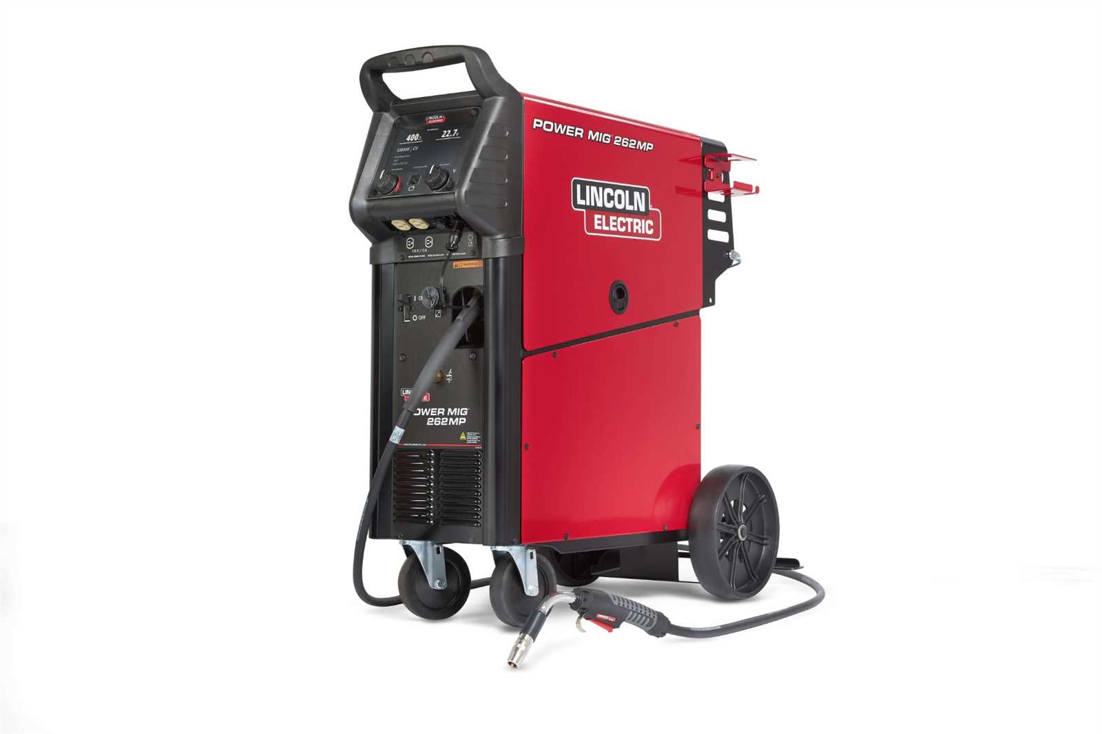
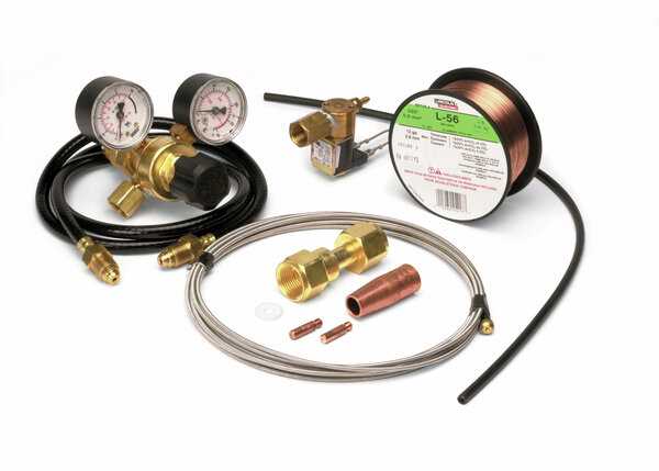
The process of joining metals involves a carefully controlled mechanism that delivers both shielding gas and filler material. This setup ensures a smooth and effective fusion by protecting the work area from contaminants and providing the necessary material to fill the gap between the metal pieces. The coordination between gas delivery and wire feed is crucial for a successful outcome.
The gas system operates to create a protective environment around the weld zone, preventing external elements from interfering with the quality of the work. Meanwhile, the wire feed mechanism continuously supplies the filler material at a consistent rate, which is key to maintaining steady progress and ensuring that the bond between metals is strong and even.
Both the gas flow and the wire feed speed can be adjusted depending on the thickness of the material and the specific requirements of the task. Proper alignment of these two components is essential for achieving clean, durable results without defects.
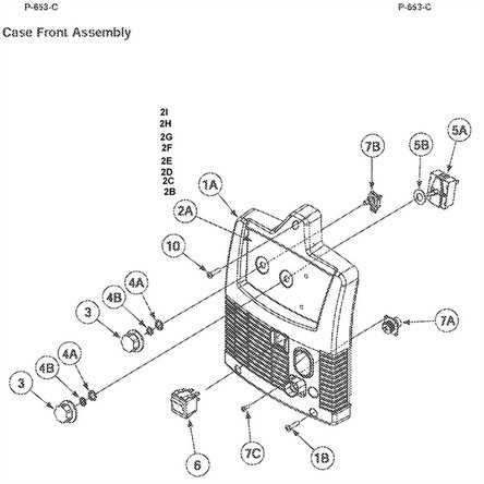
The control panel plays a pivotal role in managing the settings and overall operation of the machine. Understanding the functions of each component on the panel is crucial for effective usage, ensuring safety and precision during the work process.
The primary controls are responsible for adjusting the machine’s performance parameters. These typically include dials or switches that modify voltage, wire feed speed, and other operational factors, allowing the user to fine-tune the output according to specific requirements.
Various indicators provide real-time feedback on the system’s status, including power levels, operational readiness, and potential error alerts. These features help users monitor performance and identify issues promptly.
| Control |
Function |
| Voltage Adjuster |
Regulates the electrical output for precise control of performance. |
Power Supply and Transformer Breakdown
The power supply and transformer are critical components in any electrical device, serving to convert and regulate electrical energy for optimal performance. Understanding the functioning and potential issues within these elements is essential for effective troubleshooting and maintenance. This section will explore the various aspects of power supplies and transformers, including their roles, common problems, and possible solutions.
Functions of the Power Supply
The primary role of the power supply is to convert incoming electrical energy into a suitable form that can be utilized by the system. This process involves voltage regulation and filtering to ensure a stable output. A reliable power supply is crucial for maintaining the efficiency and longevity of the overall equipment.
Common Transformer Issues
Transformers can experience several issues, such as overheating, short circuits, and insulation breakdown. These problems can lead to decreased performance or complete failure of the device. Regular inspection and maintenance are vital to prevent these issues, ensuring the transformer operates effectively and safely.
Torch and Nozzle Assembly Overview
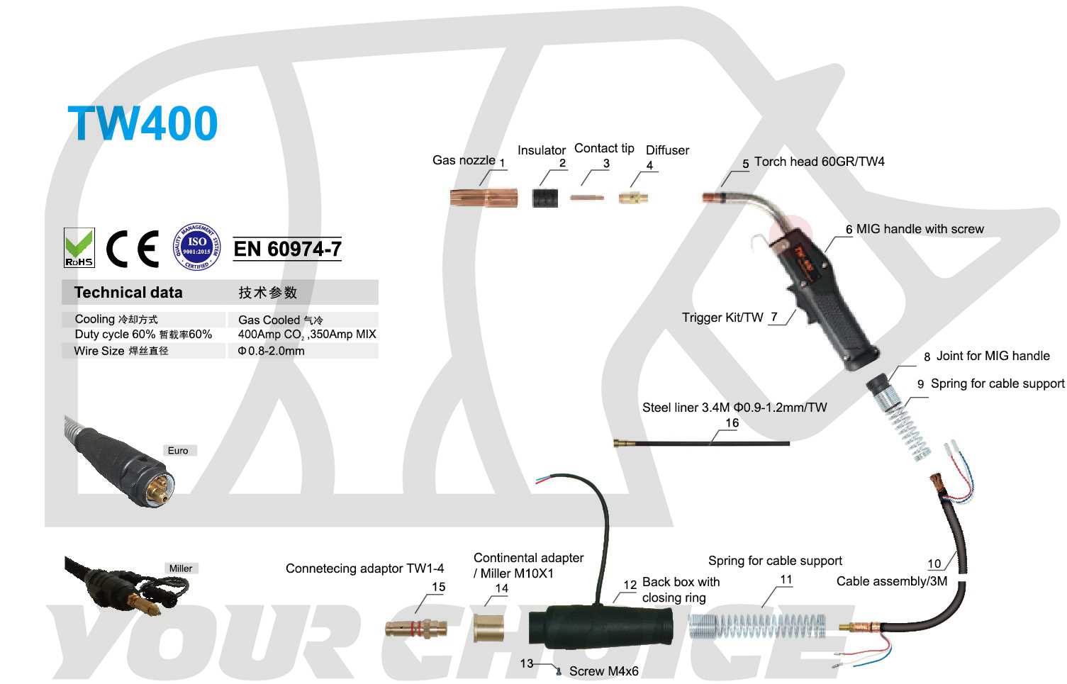
The torch and nozzle assembly is a critical component in welding applications, playing a vital role in directing the flow of gas and filler material during the welding process. This assembly ensures precise control over the weld pool, contributing to the overall quality and efficiency of the operation.
Key Components of the Assembly
This assembly typically consists of several essential parts, including the torch handle, nozzle, and contact tip. The torch handle provides a comfortable grip for the operator, while the nozzle focuses the shielding gas, protecting the weld from atmospheric contamination. The contact tip delivers the electrical current to the filler material, ensuring a strong bond.
Importance of Proper Maintenance
Regular maintenance of the torch and nozzle assembly is crucial for optimal performance. Over time, wear and tear can affect the effectiveness of these components. Inspecting and replacing worn parts can help maintain a consistent welding experience and enhance the longevity of the equipment.
Drive Rollers and Wire Feed System
The drive rollers and wire feed mechanism are essential components in the functioning of a welding apparatus. They are responsible for guiding and supplying the filler material to the welding torch, ensuring a smooth and consistent flow during operation. Properly functioning rollers and feed systems contribute to the overall efficiency and quality of the welds produced.
Drive Rollers are designed to grip the welding wire and propel it toward the welding gun. The selection of roller type, such as knurled or smooth, can impact the feeding performance and the compatibility with various wire diameters. Maintaining the rollers in optimal condition is crucial for preventing slippage and ensuring accurate wire delivery.
Wire Feed System encompasses the entire assembly that manages the movement of the filler material. This system typically includes the feed motor, drive rollers, and tension adjustments. Proper calibration of the tension ensures that the wire is fed without deformation or excessive friction, which can lead to feeding issues and inconsistent welding results. Regular inspection and maintenance of this system will help to achieve reliable performance.
Cooling Fan and Heat Dissipation Parts
Effective temperature management is essential for maintaining optimal performance in welding equipment. The components responsible for cooling and heat management play a critical role in ensuring longevity and reliability. Understanding these elements can help users troubleshoot issues and enhance the lifespan of their devices.
Cooling Fan Functionality
The cooling fan is a vital component that facilitates airflow within the machine. By circulating air, it helps to dissipate heat generated during operation. This process prevents overheating, which can lead to equipment failure. A properly functioning fan not only extends the life of the machine but also improves efficiency during use.
Heat Dissipation Mechanisms
In addition to the cooling fan, various mechanisms are in place to enhance heat dissipation. These include heat sinks and vents strategically designed to allow warm air to escape. Regular maintenance of these components is crucial to ensure effective heat management. Users should periodically inspect for dust buildup and obstructions that may hinder airflow.
Maintenance Tips for Key Parts
Proper upkeep of essential components is crucial for ensuring the longevity and optimal performance of your equipment. Regular attention to these elements can prevent potential issues and enhance efficiency. Below are some vital maintenance strategies to consider.
1. Regular Cleaning: Keeping critical areas clean helps to prevent the buildup of debris and contaminants. Utilize a soft brush or cloth to remove dirt and dust from various surfaces, ensuring all components remain free of obstruction.
2. Lubrication: Periodic lubrication of moving parts is essential to minimize friction and wear. Use appropriate lubricants for specific components, and be cautious not to over-lubricate, as this can attract more dirt.
3. Inspect for Wear: Frequent inspections of vital elements will help identify any signs of wear or damage early. Look for cracks, corrosion, or irregularities, and address any issues promptly to avoid further complications.
4. Check Electrical Connections: Ensure that all electrical connections are secure and free from corrosion. Loose or corroded connections can lead to performance issues and safety hazards.
5. Follow Manufacturer Guidelines: Always adhere to the maintenance recommendations provided by the manufacturer. These guidelines are designed to ensure the equipment operates efficiently and safely, prolonging its lifespan.
Identifying Wear and Tear in Components
Regular inspection of equipment is crucial for maintaining optimal performance and longevity. Identifying signs of deterioration in various elements can prevent potential malfunctions and enhance the overall efficiency of the device. This section will explore how to recognize and assess the wear and tear in critical components.
Common Indicators of Damage
Key signs of deterioration may include unusual noises, inconsistent performance, and visible wear on surfaces. Discoloration or chipping can also signal that a part is nearing the end of its functional life. By staying vigilant, users can address issues before they escalate into major repairs.
Regular Maintenance Practices
Implementing routine maintenance practices can significantly reduce the risk of wear-related issues. Regularly cleaning components and checking for signs of fatigue, such as cracks or excessive movement, is essential. Lubricating moving parts can also help minimize friction and prolong the lifespan of the equipment.
Replacement Guide for Common Parts
This section provides essential information on substituting frequently needed components in a specific welding device. Understanding the proper replacements can significantly enhance the machine’s performance and longevity.
First, it’s important to identify which components may require replacement over time. Commonly affected parts include the torch assembly, contact tips, and gas diffuser. Regular inspection can help detect wear and tear, ensuring timely intervention.
1. Torch Assembly: This is a critical part of the equipment that allows for precise control during operation. When it shows signs of damage, it’s advisable to replace it to maintain optimal functionality.
2. Contact Tips: These small but vital elements are responsible for transferring current to the workpiece. Over time, they can wear out, affecting the quality of the weld. Replacing contact tips regularly is essential for consistent results.
3. Gas Diffuser: This component plays a crucial role in shielding the weld area from contaminants. If it becomes clogged or damaged, it should be replaced to prevent defects in the welding process.
By paying attention to these components and replacing them as needed, operators can ensure the smooth operation of their equipment, ultimately leading to better results and a safer working environment.
