case 480c backhoe parts diagram

Understanding the layout of key mechanical assemblies is essential for effective maintenance and troubleshooting. This guide provides a clear overview of the essential components that form the structure of various machinery models, focusing on the inner workings and their interactions. With the correct visualization, users can easily identify specific elements and their connections, streamlining repairs and replacements.

In the following sections, we will examine the detailed structure, highlighting critical elements that ensure smooth operation. Through this breakdown, you can become familiar with the main mechanical units and their respective roles in the overall system’s functionality.

Whether you are maintaining, repairing, or simply seeking to better understand the machinery, this guide will serve as a valuable resource. By following the organized layout and identifying each element, you’ll enhance your knowledge and efficiency in working with complex equipment.

Overview of the Case 480C Backhoe Components
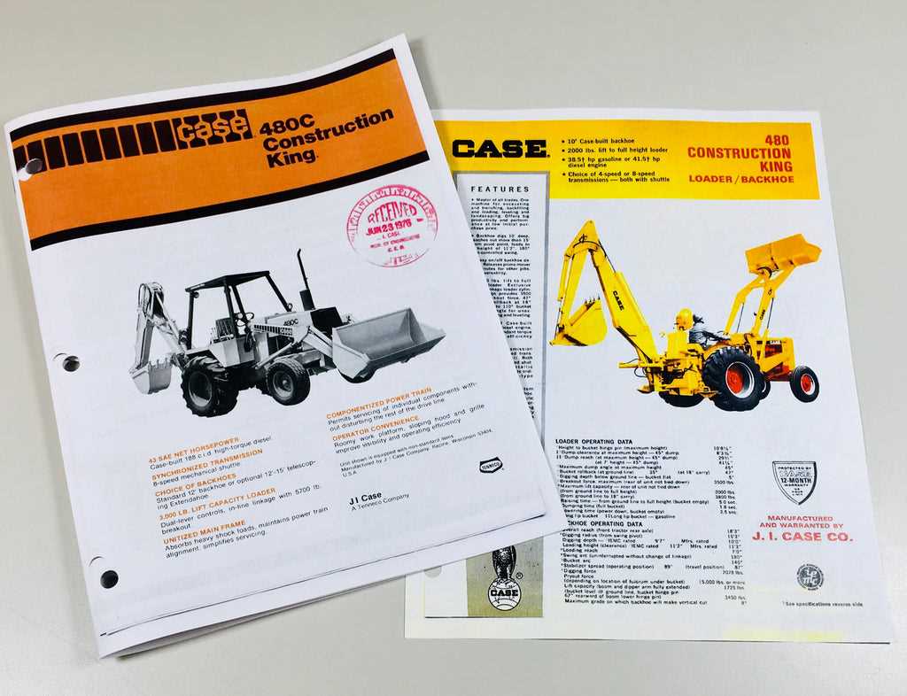
case 480c backhoe parts diagram

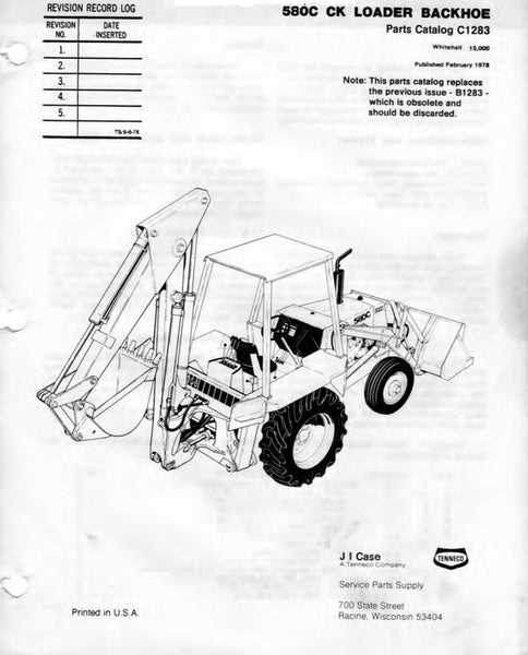
The machine is built with a range of interconnected systems designed to handle various tasks efficiently. Each part of the structure contributes to its overall functionality, ensuring reliable performance during heavy-duty operations. In this section, we’ll explore the main components, focusing on their individual roles and how they work together to form a seamless system.

Component Description
Engine The powerhouse that drives the equipment, providing the necessary force for digging, lifting, and moving.
Hydraulic System Operates the various movable parts

Main Hydraulic System Breakdown

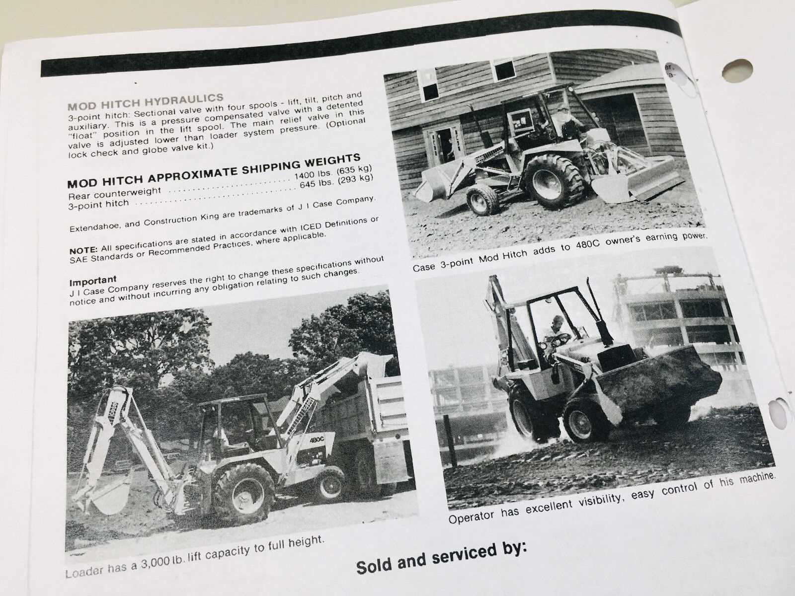
The hydraulic system plays a crucial role in ensuring the effective operation of various mechanical components. It allows for the transfer of power through fluid dynamics, enabling precise control of movements and actions. Understanding the structure and flow within this system is essential for diagnosing and maintaining its efficiency.

Key Components of the Hydraulic Network

case 480c backhoe parts diagram

The primary elements include pumps, valves, cylinders, and hoses. The pump generates pressure by moving fluid through the system, while valves control the direction and flow of the liquid. Cylinders are responsible for converting hydraulic energy into mechanical force, enabling the machine’s movements.

Fluid Flow and Control Mechanism

The hydraulic circuit is designed to manage fluid flow efficiently. This ensures that power is delivered to the right components when needed. Leaks or blockages in the system can lead to pressure loss, reducing performance. Regular checks and maintenance of hoses and seals are vital for preventing such issues.

Detailed View of the Engine Assembly

The engine assembly is a critical component of any heavy machinery, ensuring optimal performance and durability. A close examination of its structure reveals the interconnected systems that contribute to the machine’s power and efficiency. Understanding the layout of these elements is essential for maintenance and troubleshooting.

Key Components Overview

Within the engine, several vital systems work together. The combustion system, for example, powers the machine through a sequence of fuel ignition. The cooling system ensures that the temperature remains at optimal levels during operation, preventing overheating.

System Connections and Functions

The assembly includes various interconnected parts that regulate fuel flow, manage exhaust, and maintain pressure. Regular inspection of these components, along with proper lubrication, helps ensure the engine runs smoothly and avoids breakdowns. Familiarity with each system is essential for those performing repairs or upgrades.

Transmission and Drive Train Layout

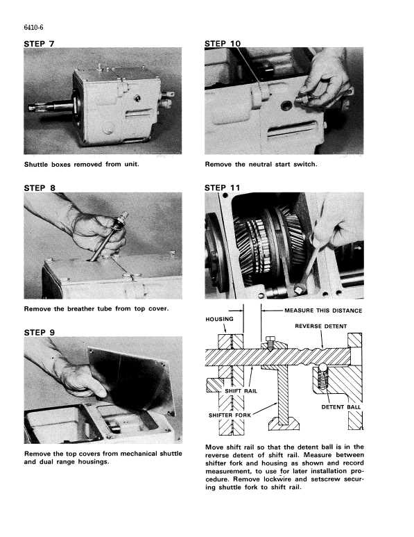
The transmission and drive train system play a crucial role in ensuring the smooth and efficient operation of the machine. These components are responsible for transferring power from the engine to the wheels, enabling movement and performance under various working conditions. A well-designed layout ensures minimal power loss and optimal coordination between different mechanical parts.

Transmission serves as the heart of the system, managing power distribution between different gears, allowing for flexibility in speed and torque. It ensures that the machine can operate efficiently whether at low speeds for precision tasks or higher speeds for quicker mobility.

Drive Train components, including axles, differentials, and shafts, work together to convert the transmitted power into forward or backward motion. These elements must be properly aligned and maintained to prevent

Electrical System and Wiring Map

The electrical system plays a crucial role in ensuring smooth operation and control of various components. A clear understanding of the wiring connections is essential for efficient troubleshooting and maintenance. This section outlines the key elements of the electrical layout, providing a comprehensive guide to the internal connections and flow of electrical currents.

Key Components of the Electrical System

The electrical network consists of several vital elements that interact to manage power distribution and functionality. These components work together to deliver electricity to essential parts and ensure the machine operates correctly.

  • Battery: Supplies power to the entire system.
  • Alternator: Recharges the battery and powers electrical components while the engine runs.
  • Starter Motor: Responsible for initiating

    Loader and Boom Mechanism Explanation

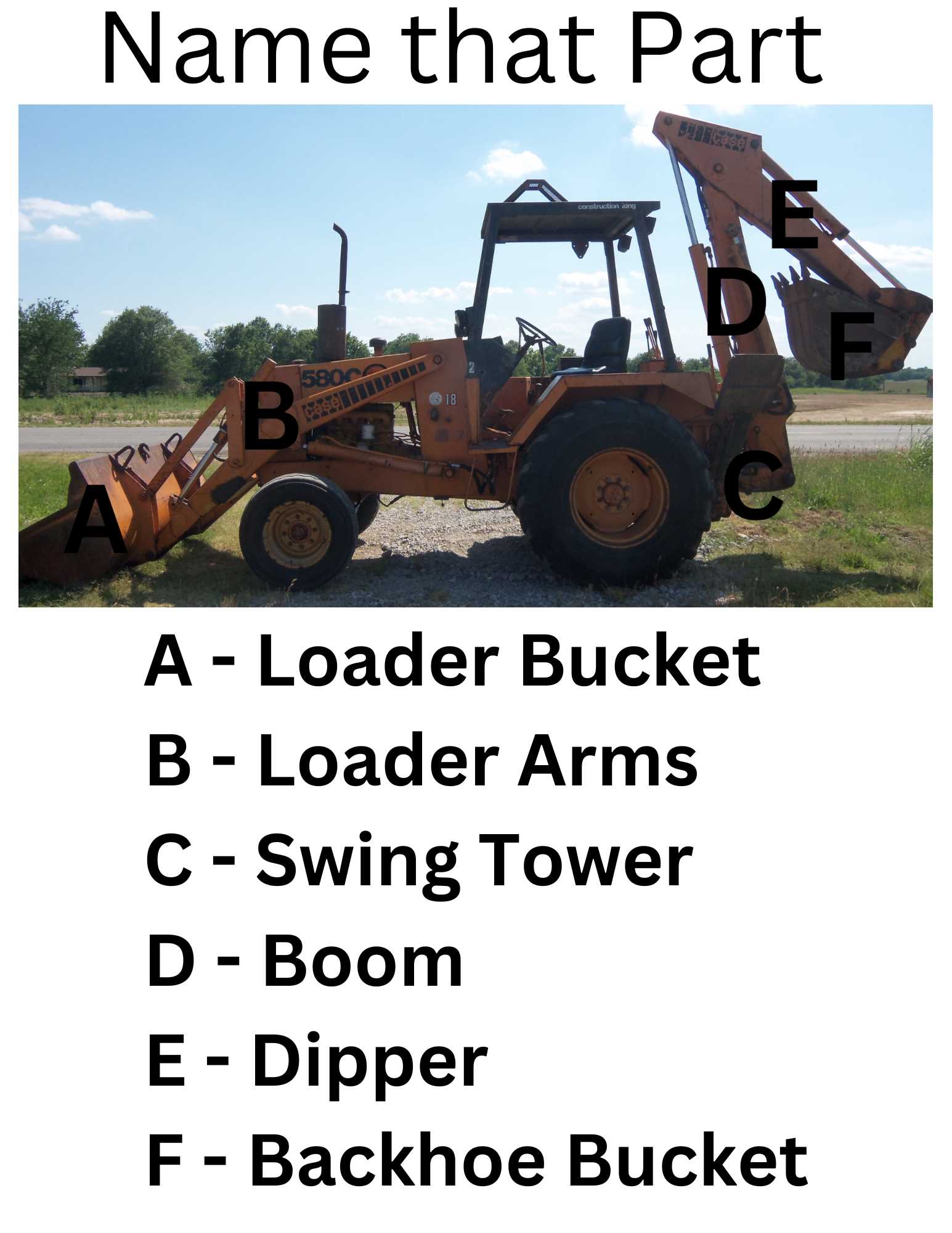
    The loader and boom mechanism is a vital component in construction machinery, designed to enhance efficiency in various lifting and digging tasks. This system consists of interconnected parts that work harmoniously to provide superior functionality, ensuring that operators can perform a wide range of activities with ease.

    At the heart of the mechanism is the boom, which is typically a long, articulating arm that allows for vertical and horizontal movement. This structure enables the equipment to reach various heights and distances, making it suitable for loading materials, excavating, or performing other heavy-duty operations. The loader, often attached to the front, is responsible for gathering and moving materials such as dirt, gravel, and debris.

    Additionally, hydraulic systems play a crucial role in the operation of the loader and boom. These systems utilize fluid power to transmit energy, allowing for precise control over the movements of the arm and bucket. The ability to adjust the angle and height of the loader enhances versatility, enabling operators to navigate challenging terrains and reach confined spaces.

    Overall, the loader and boom mechanism exemplifies engineering ingenuity, combining strength and flexibility to meet the demands of various construction and excavation projects. Understanding this system’s components and functionality is essential for optimizing performance and ensuring safe operation.

    Brake System and Pedal Assembly

    The braking mechanism is a critical component of any machinery, ensuring safe operation and control. It consists of various elements that work together to provide effective stopping power. Understanding the design and functionality of this system is essential for proper maintenance and troubleshooting.

    Components of the Brake System

    The brake system includes several key components that contribute to its overall efficiency:

    • Brake Pedals: These are the interface for the operator, allowing for manual control of the braking action.
    • Hydraulic Lines: These transport the hydraulic fluid necessary for activating the brakes.
    • Brake Cylinders: They convert the hydraulic pressure into mechanical force, engaging the braking mechanism.
    • Brake Shoes: These create friction against the drum or disc to slow down the machinery.

    Maintenance Tips

    case 480c backhoe parts diagram

    Regular maintenance is crucial to ensure the braking system operates smoothly:

    1. Check hydraulic fluid levels and top up as needed.
    2. Inspect brake pads for wear and replace them if necessary.
    3. Examine hydraulic lines for leaks or damage.
    4. Ensure that the brake pedal operates freely without obstruction.

    By following these guidelines, the efficiency and safety of the braking system can be maintained, prolonging the life of the equipment.

    Cabin Controls and Operator Interface

    case 480c backhoe parts diagram

    The interface within the operator’s enclosure is crucial for ensuring seamless interaction between the user and the machinery. This section highlights the various components and functions that facilitate control over the vehicle’s operations, contributing to efficiency and safety during tasks.

    Fundamental to the operator experience are the levers and buttons strategically positioned for ease of access. These controls allow for precise manipulation of the equipment, enabling the operator to execute movements with accuracy. The arrangement of these elements is designed to minimize unnecessary motions, enhancing comfort and reducing fatigue during prolonged usage.

    Additionally, visual indicators and displays play a significant role in providing real-time feedback. Gauges that monitor vital functions such as fuel levels, temperature, and hydraulic pressure inform the operator about the machine’s status, allowing for timely adjustments and maintenance actions. A well-organized layout not only promotes ease of use but also ensures that critical information is readily available.

    Finally, ergonomic considerations are essential in the design of the cabin. Adjustable seating and thoughtfully placed controls contribute to a more comfortable working environment, which can lead to improved focus and productivity. Ensuring that operators can easily reach and engage with all necessary functions is vital for the effective performance of the equipment.

    Cooling System and Radiator Components

    case 480c backhoe parts diagram

    The cooling mechanism is essential for maintaining optimal operating temperatures within heavy machinery. It plays a vital role in preventing overheating, which can lead to engine damage and reduced performance. Understanding the various elements involved in this system can aid in ensuring efficiency and longevity of the equipment.

    Key Components of the Cooling System

    At the heart of the cooling system lies the radiator, a critical element that dissipates heat from the coolant circulating through the engine. The radiator is complemented by other components, such as the water pump, which facilitates the flow of coolant, and the thermostat, which regulates temperature by controlling coolant circulation. Regular maintenance of these components is crucial to avoid overheating and maintain the machine’s reliability.

    Importance of Proper Maintenance

    Regular inspection and maintenance of the cooling system are necessary to ensure all components function correctly. This includes checking for leaks, ensuring the radiator is clean and unobstructed, and monitoring coolant levels. Neglecting these aspects can lead to overheating, reduced efficiency, and potential damage to the engine. By prioritizing the care of the cooling system, operators can enhance the overall performance and lifespan of their machinery.

    Steering System Parts and Functions

    The steering system is a crucial component of any machinery designed for maneuvering and precision operation. This system ensures that the operator can control the direction of the vehicle effectively, allowing for smooth navigation in various work environments. Understanding the elements involved in this system and their respective roles is essential for maintaining optimal performance and safety.

    Component Function
    Steering Wheel Allows the operator to control the direction by rotating it, which translates into movement of the wheels.
    Steering Column Connects the steering wheel to the steering mechanism, transmitting input from the operator.
    Gearbox Converts the rotational motion from the steering wheel into linear motion, facilitating wheel movement.
    Linkages Transmit force from the gearbox to the wheels, allowing for precise steering control.
    Hydraulic Cylinder Provides additional force to assist with steering, particularly in heavy machinery, enhancing responsiveness.

    By familiarizing oneself with the components of the steering system, operators can ensure that their equipment remains functional and reliable, contributing to safer and more efficient operation on the job site.

    Fuel System Components and Layout

    The fuel system of heavy machinery plays a critical role in ensuring efficient operation and performance. It consists of various elements that work together to deliver fuel to the engine while maintaining optimal pressure and flow. Understanding the layout and components of this system is essential for troubleshooting and maintenance.

    Key Components of the Fuel System

    The primary elements of the fuel system include the fuel tank, filters, pumps, and injectors. Each component serves a specific function:

    • Fuel Tank: Stores the fuel and provides a steady supply to the system.
    • Filters: Remove impurities from the fuel, preventing damage to the engine and other components.
    • Pumps: Transfer fuel from the tank to the engine, ensuring proper pressure for efficient combustion.
    • Injectors: Atomize the fuel, allowing for optimal mixing with air in the combustion chamber.

    Layout Overview

    The arrangement of these components is designed to maximize efficiency and reliability. The fuel tank is typically located at the rear of the machine, with fuel lines connecting it to the filters and pumps positioned near the engine. This strategic layout minimizes the distance fuel must travel, reducing the risk of leaks and ensuring consistent fuel delivery.

    Axle and Differential Breakdown

    The axle and differential assembly is a crucial component in various heavy machinery, providing the necessary support and power transmission to the wheels. Understanding the structure and function of this system is essential for effective maintenance and troubleshooting. This section will delve into the specifics of the axle and differential, outlining their roles and the importance of their components.

    Components of the Axle Assembly

    • Axle Shaft: This component connects the wheels to the differential and transmits torque, allowing for movement.
    • Hub: The hub houses the wheel bearings and connects the wheel to the axle shaft.
    • Brake Assembly: This part is essential for slowing down or stopping the machinery, often integrated into the axle design.
    • Seals: These prevent dirt and moisture from entering the axle housing, protecting the internal components.

    Differential Mechanism

    The differential is responsible for allowing the wheels to rotate at different speeds, which is particularly important when turning. This mechanism comprises several key components:

    1. Ring Gear: Engages with the drive gear, transferring power from the engine.
    2. Pinion Gear: This small gear meshes with the ring gear, facilitating rotation.
    3. Side Gears: These gears connect to the axle shafts, enabling independent rotation of each wheel.
    4. Spider Gears: Positioned between the side gears, these allow for the differential action during turns.

    Proper maintenance of the axle and differential components is vital for the overall performance and longevity of the machinery. Regular inspections and timely replacements of worn parts can prevent costly repairs and ensure optimal functionality.