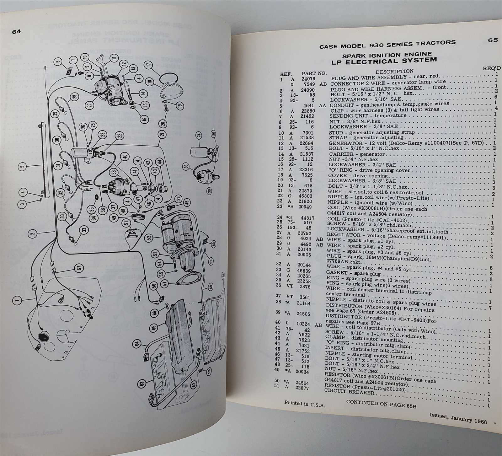
Understanding the structure and arrangement of essential elements within complex machinery is key to ensuring smooth operation and effective maintenance. This guide provides a detailed breakdown of interconnected systems, helping users quickly identify individual elements and their respective connections.
The ability to visualize how different mechanical components interact allows for precise troubleshooting and seamless repairs. With a clear layout, users can efficiently address issues, replace worn-out elements, and optimize system performance.
This resource simplifies the process by offering clear illustrations of various assemblies. Whether handling routine maintenance or in-depth restoration, having access to accurate and well-organized schemes ensures reliable results every time.
Case 930 Parts Diagram
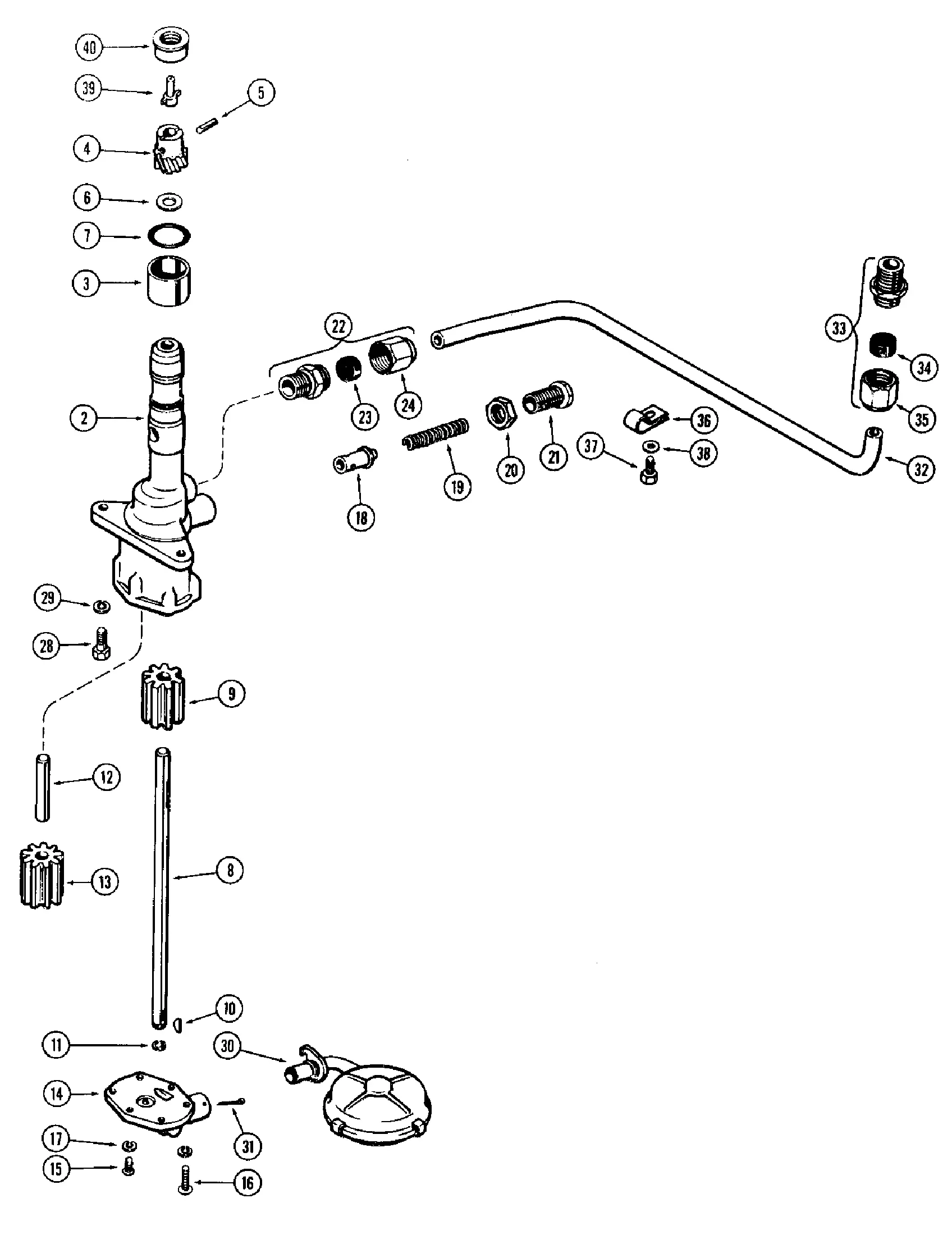
The layout of components within mechanical systems plays a critical role in maintaining efficiency and ensuring smooth operation. A detailed visual guide helps users identify individual elements, understand their placement, and recognize connections between various segments.
Structural Overview
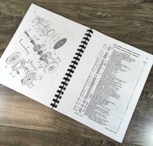
This breakdown provides an organized view of key sections, illustrating how each element integrates into the system. Such guides simplify maintenance tasks, enabling quick identification of faulty pieces and facilitating accurate replacements.
Importance of Clear Schematics
Accurate illustrations allow technicians to minimize downtime by swiftly locating necessary items. A well-structured map of elements ensures that repairs are performed correctly, reducing the likelihood of reassembly issues and enhancing long-term reliability.
Understanding Engine Layout
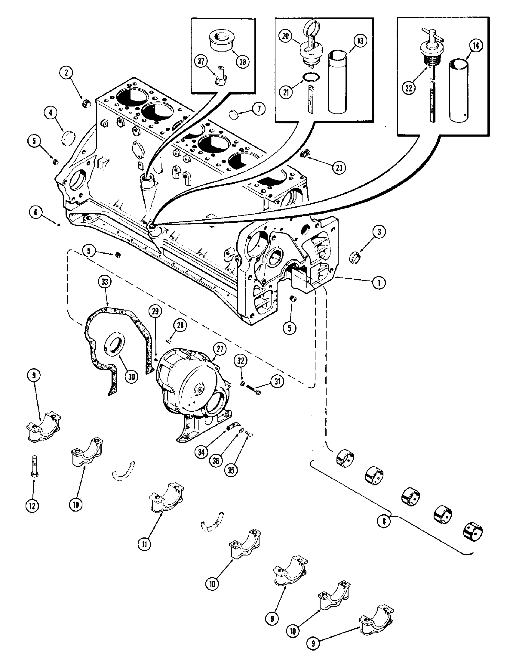
The configuration of a tractor’s motor plays a crucial role in ensuring optimal performance and efficiency. A well-organized layout helps streamline maintenance, facilitates troubleshooting, and enhances overall functionality. Recognizing the relationship between key components within the system is essential for smooth operation and prolonged service life.
The engine assembly integrates multiple elements, such as the cylinder block, pistons, crankshaft, and cooling system. These parts collaborate to generate power, control heat, and minimize friction. The motor’s arrangement allows technicians to access key areas during repairs or adjustments, ensuring that downtime is minimized and productivity remains high.
A comprehensive understanding of the engine’s internal structure can improve both preventive maintenance and timely repairs. Identifying how individual mechanisms interact helps detect potential issues early, reducing the risk of failure. Familiarity with the system layout also supports more efficient fuel use and ensures that performance targets are consistently met.
Hydraulic System Components Overview
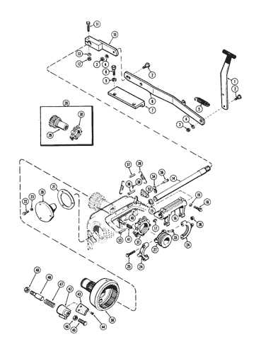
The hydraulic system relies on an interconnected network of components working together to generate and transfer fluid power efficiently. These elements ensure smooth operation and precise control, facilitating the movement of heavy loads with minimal effort. Each part contributes to maintaining pressure and directing fluid flow according to the system’s requirements.
Pumps play a vital role by converting mechanical energy into hydraulic force, ensuring consistent flow throughout the system. Valves regulate pressure and control the direction of fluid movement, enabling flexible operation under various conditions.
Reservoirs store the fluid, preventing contamination and ensuring an adequate supply during operation. Filters remove impurities, safeguarding the system from wear. Cylinders convert fluid energy into linear motion, powering mechanical actions. Hoses and pipes connect these components, forming a closed circuit that ensures reliable and safe operation.
Transmission Assembly Breakdown
The transmission assembly ensures smooth power transfer within machinery, coordinating the flow of energy between the engine and other components. A deeper understanding of its structure provides insight into maintaining efficiency and prolonging operational life.
Main Components Overview
Key elements within the transmission include gear sets, shafts, bearings, and synchronization systems. Gears manage the torque and speed ratios, while shafts act as the main support for rotational movement. Bearings reduce friction and ensure seamless rotation, enhancing longevity and performance.
Synchronization and Maintenance Tips
Synchronization mechanisms prevent gear clashes, facilitating smooth shifting. Routine inspections of oil levels, gear alignment, and bearing conditions are essential for preventing wear and tear. Timely maintenance ensures uninterrupted functionality and reduces downtime.
Steering Mechanism Key Elements
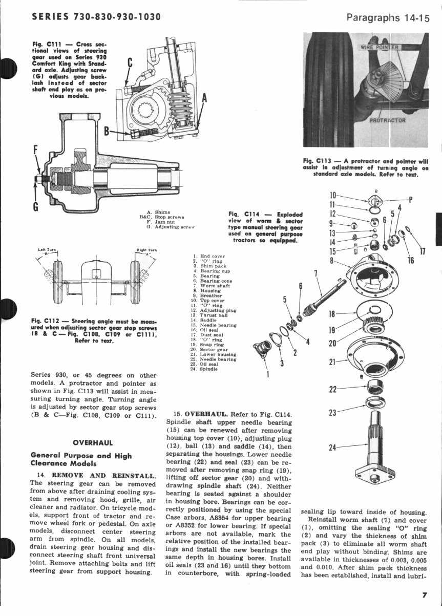
The steering system ensures smooth control and maneuverability, allowing precise handling in various conditions. It comprises interconnected components, each playing a vital role in transmitting motion and ensuring stability during operation.
- Steering Wheel: The main interface through which the operator controls direction, converting rotational input into mechanical movement.
- Steering Column: A link between the steering wheel and other parts of the system, transmitting motion downward with minimal resistance.
- Pitman Arm: Transfers rotational motion from the steering box to the linkage, ensuring accurate directional changes.
- Drag Link: A crucial connector between the pitman arm and steering knuckle, maintaining alignment during movement.
- Tie Rods: Stabilize and synchronize the wheels, ensuring consistent angles during turns for precise handling.
- Hydraulic Pump (
Fuel System Parts Identification
The efficiency of a machine’s operation heavily relies on its fuel delivery components. Understanding the various elements within this system is crucial for optimal performance and maintenance. Each component plays a significant role in ensuring that fuel is supplied efficiently and effectively to the engine, thus impacting overall functionality.
Key Components
Recognizing the essential elements of the fuel delivery system can aid in troubleshooting and repair processes. Below is a summary of the major components that contribute to the system’s operation:
Component Function Fuel Tank Stores the fuel until needed by the engine. Fuel Pump Moves fuel from the tank to the engine. Fuel Filter Removes impurities from the fuel before it reaches the engine. Fuel Injector Atomizes the fuel for efficient combustion in the engine. Importance of Proper Maintenance
Maintaining the integrity of the fuel delivery system is essential for prolonging the life of the machinery. Regular checks and replacements of filters, pumps, and other components can prevent performance issues and ensure that the system operates smoothly. Proper identification and understanding of each element will lead to more efficient maintenance practices.
Cooling System Diagram Explained
The effective operation of any machinery relies heavily on its thermal management system. This section delves into the components and functions of a cooling assembly, illustrating how it maintains optimal temperature levels to prevent overheating and ensure efficiency.
Key Components
- Radiator: Responsible for dissipating heat absorbed from the engine.
- Water Pump: Circulates coolant through the system to maintain flow.
- Thermostat: Regulates coolant temperature and flow based on engine requirements.
- Coolant Hoses: Facilitate the movement of coolant between various components.
- Fan: Enhances airflow over the radiator to improve heat dissipation.
Functionality Overview
- The water pump draws coolant from the reservoir and circulates it through the engine.
- As the engine operates, it generates heat, which is absorbed by the coolant.
- The heated coolant is then directed to the radiator, where it releases heat into the atmosphere.
- The thermostat monitors temperature and adjusts coolant flow to maintain optimal operating conditions.
- Finally, the fan assists in cooling by increasing airflow, especially at lower speeds.
Brake System Components Mapping
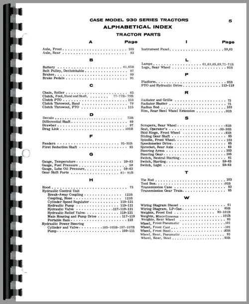
The braking system is crucial for ensuring the safety and functionality of any machinery. Understanding the various elements that make up this system is essential for maintenance and repair. Each component plays a significant role in the overall performance, contributing to effective stopping power and control.
Main Components
- Brake Pedal: The interface through which the operator engages the braking mechanism.
- Brake Booster: A device that amplifies the force applied to the brake pedal, enhancing stopping efficiency.
- Master Cylinder: Converts the mechanical force from the pedal into hydraulic pressure, transmitting it to the braking system.
- Brake Lines: Hoses that carry the hydraulic fluid from the master cylinder to the brake units.
- Brake Calipers: Components that house the brake pads and apply pressure to them against the rotor.
- Brake Pads: Friction materials that create the necessary grip to slow down or stop the machine.
- Brake Rotors: Metal discs that work in conjunction with the brake pads to provide stopping power.
Additional Elements
- Brake Fluid: The hydraulic fluid that transfers force within the braking system.
- Anti-lock Braking System (ABS): A safety feature that prevents wheel lock-up during braking.
- Parking Brake: A secondary braking mechanism that keeps the machinery stationary when not in use.
Electrical System and Wiring Layout
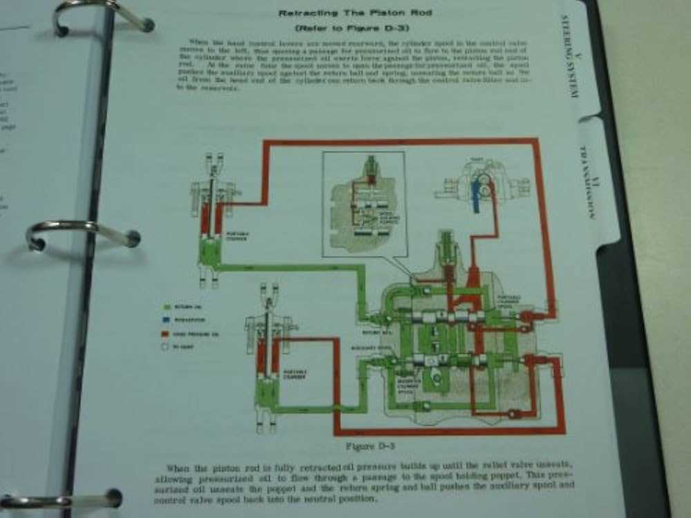
The electrical infrastructure within a machinery framework is crucial for its optimal functionality. A well-organized wiring arrangement ensures that all components communicate efficiently, facilitating the smooth operation of the equipment. Understanding the configuration and connections of the electrical components is essential for maintenance and troubleshooting.
Components Overview
The electrical system comprises various elements that work together to power the machinery. Key components include batteries, alternators, switches, and fuses. Each part plays a significant role in delivering electricity and ensuring safety during operation.
Wiring Configuration
The layout of wiring is designed to minimize interference and maximize efficiency. Proper routing of wires helps prevent damage and simplifies repairs. Below is a table summarizing the essential components and their functions within the electrical system:
Component Function Batteries Provide the necessary power to start the machinery and support electrical systems. Alternators Generate electricity to recharge the batteries and power electrical components while the machine is running. Switches Control the flow of electricity to various parts, allowing operators to manage different functions. Fuses Protect the electrical system by interrupting the current in case of overloads. Chassis Structure and Frame Parts
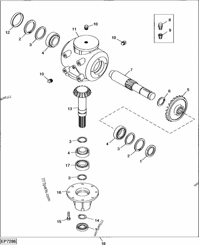
The chassis serves as the backbone of a vehicle, providing essential support and stability during operation. Understanding its components is crucial for maintenance and repairs, as these elements contribute to overall performance and durability.
Key elements of the chassis structure include:
- Frame: The primary structure that supports the entire vehicle, usually constructed from robust materials to withstand stress and impact.
- Crossmembers: Horizontal members that reinforce the frame, enhancing rigidity and load distribution.
- Suspension Mounts: Attachments for the suspension system, which absorb shocks and provide a smooth ride.
- Engine Mounts: Secure the engine to the chassis, minimizing vibration and maintaining alignment.
- Transmission Mounts: Support the transmission unit, ensuring it is firmly attached while allowing for necessary movement during operation.
In addition to these main components, various brackets and supports play vital roles in maintaining the integrity of the overall structure. Regular inspection and maintenance of these elements are essential for optimal performance and safety.
Clutch Assembly Components Overview
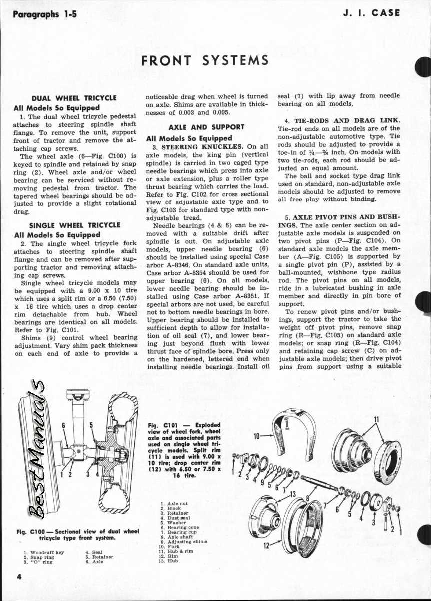
The clutch assembly plays a vital role in the operation of machinery, facilitating the transfer of power from the engine to the transmission system. Understanding its various components is essential for effective maintenance and troubleshooting. Each part contributes to the overall functionality, ensuring smooth engagement and disengagement during operation.
Component Description Pressure Plate This component applies pressure to the clutch disc, allowing for power transfer when engaged. Clutch Disc The friction surface that engages with the pressure plate to transmit torque from the engine. Flywheel A heavy disc that provides a stable platform for the clutch assembly and helps maintain engine momentum. Release Bearing This part allows for smooth disengagement of the clutch by pushing against the pressure plate. Clutch Fork A lever that connects the release bearing to the operating mechanism, enabling actuation of the clutch.