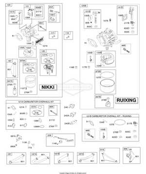
In the world of machinery and equipment, visual representations of intricate systems are essential for effective maintenance and repair. These illustrations provide a comprehensive overview, highlighting how various elements interact and function together. By examining these visuals, users can gain insight into the complexities of their devices.
Detailed schematics not only aid in troubleshooting but also enhance the overall understanding of mechanical assemblies. They serve as a vital tool for technicians and enthusiasts alike, offering clarity on the placement and role of each individual unit within the larger structure. Through these representations, one can delve into the ultimate mechanics behind performance and reliability.
Ultimately, familiarizing oneself with these comprehensive layouts empowers users to approach repairs with confidence. Whether you are a seasoned expert or a novice, these resources are invaluable in mastering the intricacies of your equipment.
Understanding the 31R977 Parts Diagram
Grasping the intricacies of mechanical schematics is essential for effective maintenance and repair. These visual aids serve as crucial references, highlighting the relationships and functions of various components. By delving into the specifics, one can enhance their understanding and efficiency in handling complex assemblies.
Key Components and Their Functions
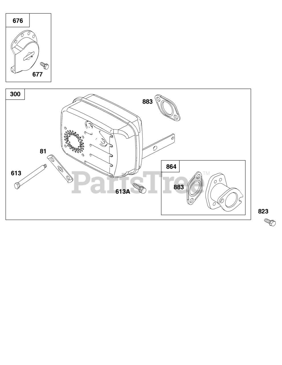
Each element in the schematic plays a vital role in the overall system. Familiarizing oneself with these elements can streamline troubleshooting and improve repair accuracy.
| Component | Function |
|---|---|
| Motor | Provides the necessary power to operate the system. |
| Gearbox | Transmits power and modifies torque and speed. |
| Control Unit | Manages operations and ensures optimal performance. |
Interpreting the Visual Representation
Understanding how to read these visuals allows for a more effective approach to assembly and disassembly. Recognizing symbols and connections can significantly reduce errors during repairs.
Key Components of 31R977 Model
This section provides a detailed overview of the most essential elements that make up the specific design. Understanding these elements will help users maintain and service the unit more efficiently, ensuring its longevity and performance.
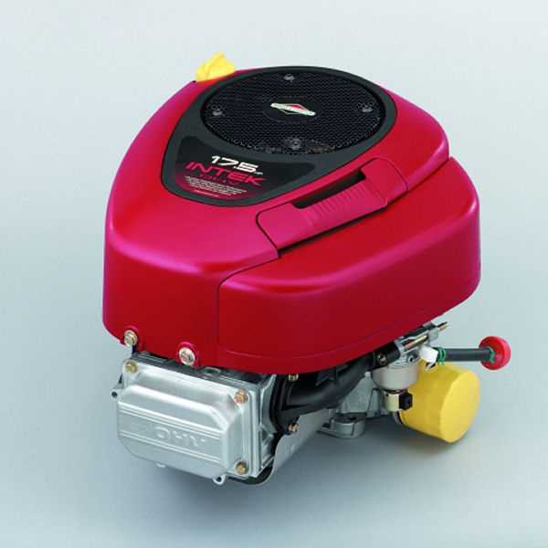
Engine Assembly: The heart of the system, this component is responsible for driving all the major functions. It includes several intricate mechanisms that work together to deliver optimal power and performance.
Transmission System: Responsible for ensuring smooth operation and transferring energy to various sections, this system allows the machine to operate under different conditions without losing efficiency.
Control Panel: This interface allows users to manage and adjust various functions. Designed for ease of use, it provides clear indicators and buttons to control performance settings.
Cooling Mechanism: This essential part ensures that all components remain within safe temperature limits during extended use. By efficiently dissipating heat, it protects the system from overheating and wear.
These key elements work together to form a reliable and durable machine, ensuring that it meets the needs of users in a variety of settings.
How to Read a Parts Diagram
Understanding technical illustrations is crucial for anyone working with complex equipment. These visual guides simplify the identification and location of various components within a machine or system, helping to streamline repairs, maintenance, or assembly.
When approaching a technical illustration, it’s important to follow a structured method to ensure accuracy. Below are some key steps to keep in mind:
- Identify the overall layout – this helps in understanding the arrangement of components.
- Look for numbering or labeling systems – these often correlate with a legend or list for easy reference.
- Examine how each item connects or interacts with others – this can clarify the function and position of the components.
By following these steps, you can efficiently navigate even the most intricate technical drawings, ensuring that you find the right component for the task at hand.
Common Issues Identified by Diagrams
Visual representations of mechanical systems often help pinpoint typical malfunctions that occur during the operation of complex equipment. They offer a clear overview of potential weak points, enabling quicker identification of the source of a problem and facilitating smoother maintenance.
Below is a table highlighting some frequent operational challenges and the possible root causes based on system visuals:
| Issue | Potential Cause |
|---|---|
| Irregular functioning | Misalignment of internal components |
| Frequent overheating | Obstruction in cooling pathways |
| Noise during operation | Wear or damage to moving elements |
| Reduced efficiency | Debris accumulation in critical areas |
Importance of Accurate Part Identification
Precise identification of components is essential for maintaining the functionality and longevity of any machinery or equipment. Incorrectly matching items can lead to compatibility issues, increased wear, or even damage to the entire system. By ensuring each element is correctly identified, businesses can avoid unnecessary downtime and reduce the risk of costly repairs.
Additionally, accurate selection promotes efficient maintenance routines and supports long-term operational reliability. This approach helps streamline supply chain processes, minimizing delays and ensuring that all necessary elements are available when needed.
| Benefit | Description |
|---|---|
| Increased Efficiency | Reduces downtime by ensuring correct replacements are used. |
| Cost Reduction | Avoids expensive repairs due to incompatible components. |
| Long-Term Reliability | Supports consistent system performance and reduces future risks. |
Comparing 31R977 with Other Models
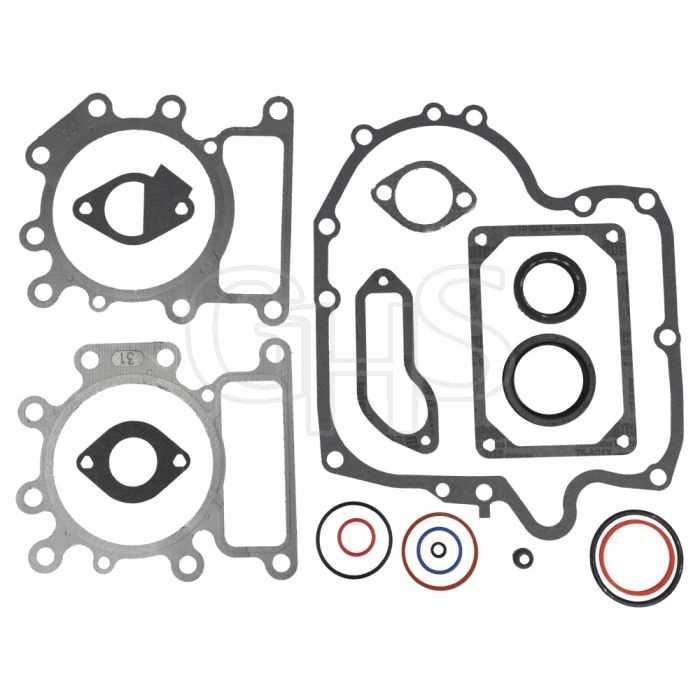
When evaluating various equipment, it’s essential to consider how they differ in terms of functionality, reliability, and design. Although some options may seem similar at first glance, subtle differences can impact their performance and suitability for specific tasks. Below, we explore these distinctions to provide a clearer understanding of how various models stand out in their respective categories.
| Feature | Model A | Model B | Model C |
|---|---|---|---|
| Durability | High | Medium | High |
| Efficiency | 85% | 90% | 80% |
| Design Complexity | Simple | Moderate | Complex |
Where to Find Replacement Parts
When it comes to finding substitutes for mechanical components, having access to reliable sources is essential. There are various platforms, both online and offline, that provide a wide range of options for those seeking to restore functionality to equipment. Knowing where to look can save time and ensure the right items are acquired for the task.
Authorized Dealers
The best option for securing authentic pieces is through certified vendors. These suppliers work directly with manufacturers to provide high-quality products that meet industry standards. Using authorized sources guarantees that the items are compatible and built to last.
Online Marketplaces
For a more convenient approach, digital stores offer a vast selection. These platforms typically include detailed descriptions and customer reviews, making it easier to choose the correct solution. Be sure to verify the credibility of the seller before making a purchase.
| Source | Advantages | Considerations |
|---|---|---|
| Certified Vendor |
