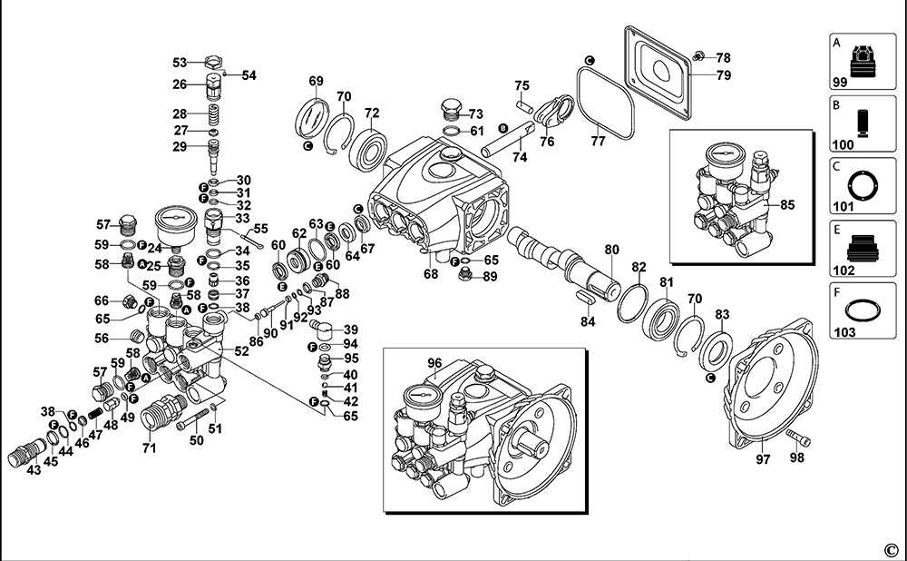
When it comes to maintaining or repairing any complex device, a clear understanding of its various elements is essential. Each unit is made up of multiple interconnected pieces that must work together seamlessly to ensure proper functionality. In this section, we will explore the structure and inner workings of the BG 55, breaking down its individual sections and examining their roles in the overall system.
The BG 55 is known for its durability and efficiency, but over time, certain sections may require closer inspection or replacement. To assist in this, it is important to familiarize yourself with the different assemblies and their purpose within the unit. By doing so, you will gain a deeper appreciation for how the equipment operates and how each part contributes to its overall performance.
Our aim is to guide you through the internal structure of the BG 55, helping you better understand how each section is designed and how they function together. This will not only help in routine maintenance but also make troubleshooting more effective when any issues arise.
Overview of the BG 55 Model
The BG 55 is a reliable and efficient tool designed for various outdoor applications. Known for its durability and ease of use, it has become a popular choice among homeowners and professionals alike. This model stands out due to its effective performance in handling demanding tasks, while maintaining a user-friendly design that caters to both beginners and experienced operators.
Key Features and Design
With its robust construction, the BG 55 is built to withstand tough environments. It incorporates modern engineering to provide consistent functionality, while remaining lightweight and easy to handle. The streamlined design also contributes to its portability, making it convenient for prolonged usage without causing fatigue. Additionally, its controls are positioned ergonomically, allowing for smooth operation and quick adjustments as needed.
Performance and Efficiency
In terms of performance, the BG 55 delivers power and precision, ensuring that each task is completed with minimal effort. The model’s engineering emphasizes fuel efficiency, reducing overall consumption while maintaining optimal output. This balance of power and efficiency makes it a cost-effective solution for a wide range of outdoor maintenance tasks.
Key Components in BG 55 Engine
The BG 55 engine is built with several essential elements that work together to ensure reliable performance. Each component plays a specific role in maintaining the overall efficiency and power output of the machine. Understanding the core elements provides insight into how the engine operates as a cohesive unit.
Main Structural Elements
- Cylinder: The heart of the engine where combustion takes place, converting fuel into mechanical energy.
- Piston: Moves within the cylinder, transmitting energy to the crankshaft, which powers the device.
- Crankshaft: Converts the up-and-down motion of the piston into rotational energy.
Fuel and Ignition System
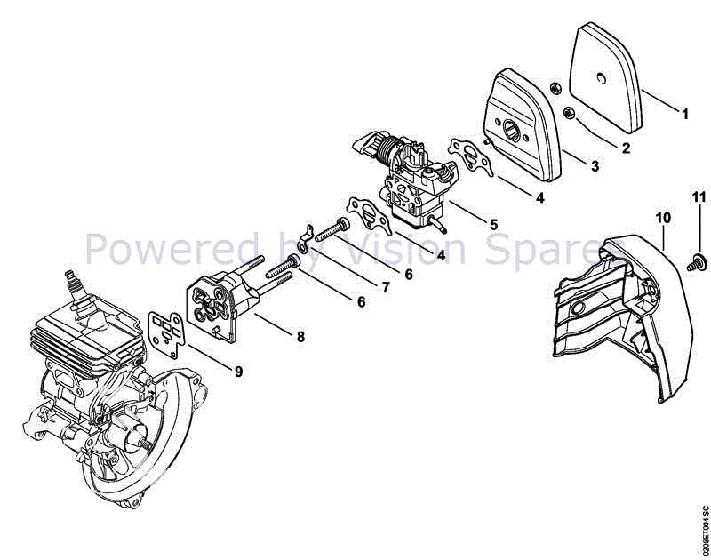
- Carburetor: Mixes air and fuel in the correct ratio for efficient combustion.
- Spark Plug: Ignites the fuel-air mixture, generating the explosion that drives the piston.
- Fuel Filter: Ensures clean fuel is delivered to the engine, preventing debris from causing damage.
These essential components, when maintained properly, ensure the engine operates smoothly and delivers consistent
Air Filtration System Breakdown
The filtration mechanism is essential for ensuring clean air flow, maintaining optimal operation by preventing unwanted substances from entering critical components. It operates through multiple layers that trap particles, ensuring the system functions efficiently and remains free from harmful contaminants. A well-maintained system prolongs the overall lifespan and enhances performance.
Primary Filter: The first layer acts as the initial defense, capturing larger particles and debris. It helps in reducing the load on the subsequent filtration stages, allowing the system to maintain consistent airflow.
Secondary Stage: This section is designed to trap finer contaminants that manage to pass through the primary filter. Typically composed of a more dense material, it ensures that even microscopic particles are intercepted, protecting the interior mechanisms.
Maintenance and Replacement: Regular inspection and timely replacement of the filtration elements are crucial to ensure maximum efficiency. Over time, the accumulation of particles can obstruct airflow, reducing the system’s overall performance. Proactive care ensures longevity and consistent functionality.
Throttle Assembly and Its Parts
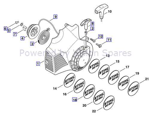
The throttle assembly plays a crucial role in regulating the engine’s performance, ensuring smooth acceleration and control. It is a system that integrates multiple components, each contributing to the overall function of managing airflow and fuel delivery. Understanding the structure and how these elements interact is essential for maintaining efficiency and functionality.
Main Components of the Throttle System
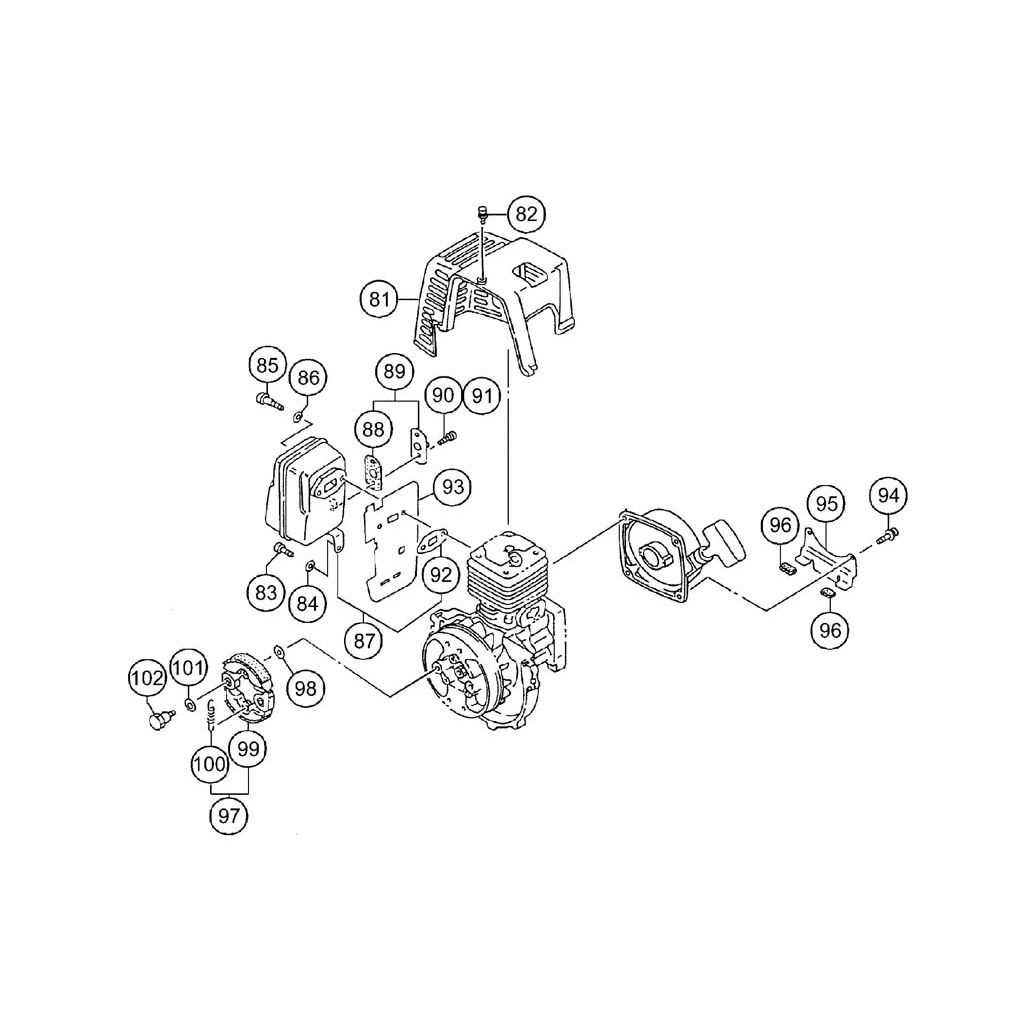
The core of the throttle assembly includes various mechanisms designed to control the engine’s power output. The throttle body, often positioned between the air intake and the engine, regulates the amount of air entering the combustion chamber. Coupled with sensors, it ensures the right balance of air and fuel, crucial for smooth operation. Another key element, the throttle cable, links the pedal to the throttle body, allowing the driver to adjust airflow with precision.
Additional Mechanisms and Their Functions
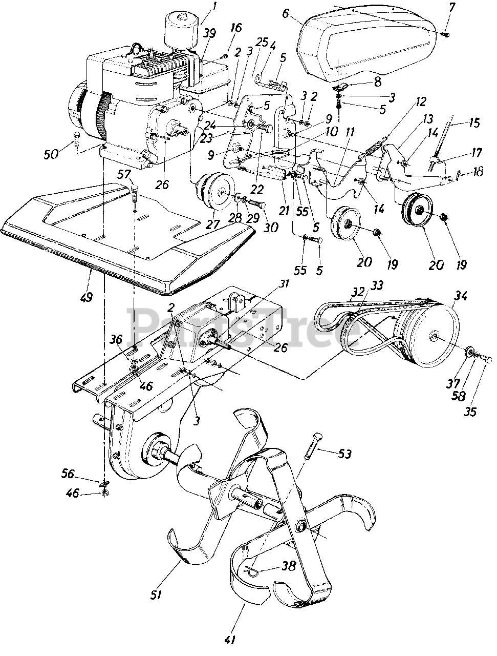
Besides the main elements, supplementary devices play vital roles. The throttle position sensor tracks the position of the throttle valve, transmitting data to the vehicle’s control unit for real-time adjustments. Meanwhile, a spring mechanism ensures that the throttle returns to its original position after being engaged, preventing unwanted acceleration. These smaller mechanisms, though often overlooked, are critical for ensuring safety and reliability.
Understanding the Ignition System
The ignition system is a critical component responsible for ensuring that the engine operates efficiently. It manages the process of initiating combustion, turning energy into motion. This system coordinates multiple elements to create the necessary spark for engine ignition.
- The first element is responsible for generating an electrical charge. This charge is directed towards creating the spark needed for combustion.
- Another part controls the timing, ensuring that the spark occurs at the optimal moment during the engine’s cycle.
- Finally, a system of wires and connectors transmits the necessary signals and energy throughout the engine, ensuring smooth operation.
Each element works together, creating a seamless sequence that allows the engine to run reliably under various conditions. Understanding how these elements interact can help diagnose potential issues and improve overall performance.
Fuel Tank and Fuel Line Configuration
The arrangement of the fuel reservoir and associated conduits is crucial for the optimal functioning of the machinery. Understanding this configuration ensures proper fuel delivery, preventing potential issues that could arise from improper setup or malfunctioning components.
In this section, we will explore the key aspects of the fuel reservoir and fuel line setup, focusing on their roles and interconnections:
- Fuel Reservoir: The primary container that stores the fuel required for operation. It is designed to withstand pressure and prevent leaks.
- Fuel Lines: These conduits transport fuel from the reservoir to the engine. They must be securely connected and free from obstructions.
- Filters: Installed along the fuel lines to remove impurities and contaminants, ensuring that only clean fuel reaches the engine.
- Connections: Each junction between the reservoir and lines must be tightly sealed to prevent leaks and ensure efficient fuel transfer.
- Ventilation: Proper venting of the fuel tank is essential to maintain pressure and prevent vacuum formation that could impede fuel flow.
Regular inspection and maintenance of these components are essential to ensure reliability and performance. A well-maintained fuel system contributes significantly to the longevity and efficiency of the machinery.
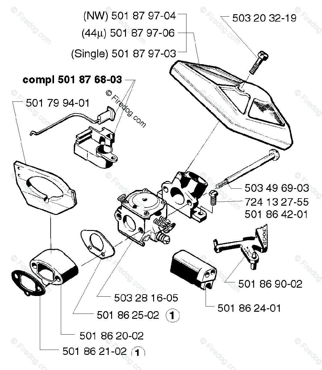
Carburetor Components Overview
The carburetor is a crucial element in the engine’s fuel system, responsible for mixing air and fuel to ensure efficient combustion. Understanding its various elements can enhance the performance and longevity of the vehicle. Below is an overview of the key components found in a typical carburetor.
- Throttle Valve: Regulates the amount of air-fuel mixture entering the engine, controlling engine speed and power output.
- Float Chamber: Maintains a consistent level of fuel, allowing the carburetor to function optimally during different operating conditions.
- Jet: A small orifice that determines the fuel flow rate into the airstream, influencing engine performance and fuel efficiency.
- Needle Valve: Works in conjunction with the float to control fuel entry into the chamber, ensuring proper fuel levels are maintained.
- Choke: A mechanism that restricts airflow, enriching the air-fuel mixture during cold starts for easier ignition.
- Air Filter: Prevents dirt and debris from entering the carburetor, protecting internal components and ensuring clean combustion.
Each of these elements plays a vital role in the overall functionality of the carburetor, contributing to the smooth operation of the engine.
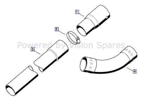
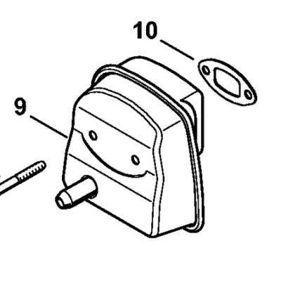
Detailed Diagram of the Muffler Section

The muffler assembly plays a crucial role in regulating sound emissions and ensuring optimal performance within the system. This component is designed to minimize noise while enhancing exhaust flow, contributing to the overall efficiency of the engine. Understanding the intricacies of this segment can greatly aid in maintenance and troubleshooting processes.
The structure typically comprises various elements, including inlet and outlet pipes, resonators, and baffles, all strategically positioned to facilitate sound attenuation. Each element works in concert to create a balance between noise reduction and exhaust gas expulsion. By analyzing the layout, one can identify potential areas for improvement or wear, allowing for timely interventions to maintain peak functionality.
Moreover, the materials used in the construction of the assembly are selected for their durability and resistance to corrosion, ensuring a long service life even under extreme conditions. Familiarity with the arrangement and purpose of each element is essential for any technician or enthusiast aiming to optimize the system’s performance and longevity.
Clutch System Components Explained
The clutch system is a critical aspect of any mechanical transmission, enabling the smooth transfer of power between the engine and the drivetrain. This system consists of various elements that work together to engage and disengage the connection, allowing for seamless gear shifts and enhanced vehicle control.
Friction Disc: The friction disc is a vital component that provides the necessary grip for power transmission. It is typically made of durable materials designed to withstand high temperatures and wear, ensuring longevity and efficiency in the system.
Pressure Plate: The pressure plate exerts force on the friction disc, keeping it in contact with the flywheel. Its design and strength are crucial for maintaining adequate pressure, allowing for effective engagement and disengagement during shifting.
Release Bearing: This component facilitates the disengagement of the clutch when the driver presses the pedal. It allows the pressure plate to move away from the friction disc, enabling smooth transitions between gears.
Flywheel: The flywheel serves as a mounting surface for the friction disc and helps store rotational energy. Its mass and design are essential for maintaining engine smoothness and minimizing vibrations during operation.
Clutch Fork: The clutch fork connects the release bearing to the clutch pedal, translating pedal movement into mechanical action. It ensures precise engagement and disengagement of the clutch, contributing to the overall performance of the system.
Understanding these components and their functions is essential for diagnosing issues and maintaining optimal performance in any mechanical system reliant on effective power transmission.
BG 55 Starter Mechanism Overview
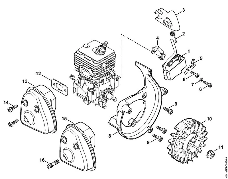
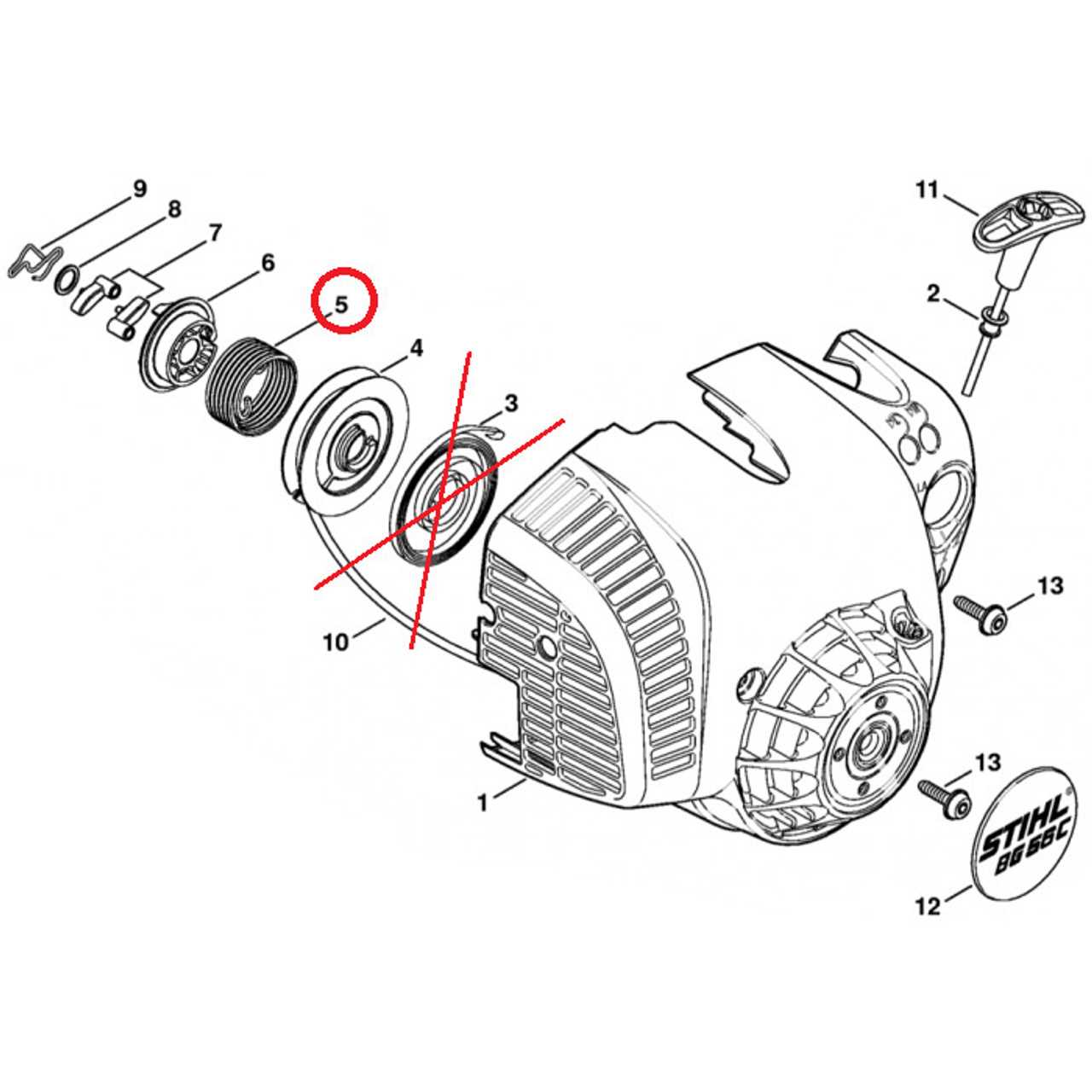
The starter mechanism of the BG 55 is a vital component that ensures the efficient initiation of the engine’s operation. This assembly plays a crucial role in converting mechanical energy into motion, facilitating the overall functionality of the device. Understanding its structure and operation can enhance maintenance and troubleshooting processes.
Key Functions of the Starter Mechanism
This assembly primarily serves to engage the engine when ignition is required. It operates through a series of interconnected elements that work harmoniously to achieve a successful start. The mechanism’s design is optimized for reliability and durability, ensuring that users experience minimal interruptions during operation.
Components and Their Roles
Within the starter mechanism, several components collaborate to perform their specific functions. Engagement gear plays a pivotal role in linking the starter to the engine, while the spring system ensures that the mechanism returns to its original position after use. Each element is engineered to withstand varying conditions, contributing to the overall performance and longevity of the BG 55.
Maintenance Tips for BG 55 Parts
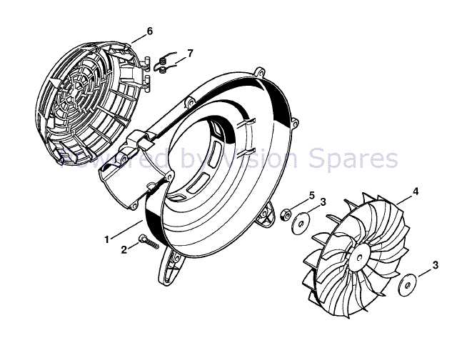
Proper upkeep is essential for ensuring the longevity and performance of your equipment. Regular checks and servicing can prevent issues that may arise from wear and tear. By following a few simple guidelines, you can keep your machinery running smoothly and efficiently.
Routine Inspections: Schedule frequent inspections to identify any signs of damage or wear. Look for cracks, rust, or any unusual noises during operation. Early detection can save you from costly repairs and downtime.
Cleaning: Keeping components clean is crucial for optimal functionality. Use appropriate cleaning solutions and tools to remove debris and dirt. Avoid harsh chemicals that could cause corrosion or damage.
Lubrication: Ensure that moving elements are adequately lubricated to reduce friction and wear. Apply the right type of lubricant as specified in the manual, and avoid over-lubricating, which can attract dust and debris.
Storage: If you need to store your equipment for an extended period, ensure it is in a dry, clean environment. Protect it from moisture and extreme temperatures to prevent degradation of materials.
Follow Manufacturer Guidelines: Always adhere to the maintenance schedule and recommendations provided by the manufacturer. This ensures that you are using the equipment safely and effectively, prolonging its lifespan.
By implementing these maintenance tips, you can enhance the performance and reliability of your BG 55, ensuring it operates at its best for years to come.