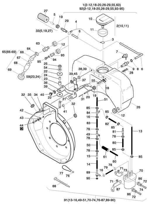
When it comes to maintaining outdoor machinery during the colder months, understanding the layout of essential elements is key to ensuring optimal performance. Proper knowledge of how various segments fit together allows for efficient troubleshooting and replacement when necessary. This guide aims to offer a clear and organized view of the internal structures involved in your equipment.
Familiarity with these configurations is crucial for anyone looking to extend the lifespan of their machine. By learning how different elements interact and contribute to the overall function, you can stay ahead of potential issues. This resource will help identify each part’s role, making it easier to conduct routine checks and perform necessary fixes with confidence.
With this insight, even complex setups become easier to navigate. Our detailed breakdown provides both clarity and convenience for those looking to maintain their devices in peak condition throughout the winter season.
Overview of Snowblower Component Layout
The layout of a machine designed for clearing snow involves several essential mechanical systems that work together to ensure efficient operation. These systems include the mechanisms responsible for collecting and moving the snow, the drive system, and the controls that allow the user to navigate and adjust settings. Understanding the positioning and functionality of these elements is crucial for both maintenance and optimal performance.
Main Mechanisms
At the core of the design, the collection system consists of rotating blades or augers that gather and break down the snow. These components are positioned at the front, where they interact directly with the snow, preparing it for further movement through the chute. The expulsion system, typically located above or behind the collection unit, is responsible for projecting the snow away from the cleared path.
Drive and Control Systems
The propulsion and steering mechanisms are housed within the lower section of the machine. T
Understanding the Drive System Mechanism
The drive system plays a crucial role in ensuring the smooth operation and movement of the equipment. It is responsible for transferring power efficiently, allowing for seamless functionality during usage. By understanding how this mechanism operates, one can gain insight into how various components work together to enable controlled motion and precise performance.
Key components in the drive system include elements that manage power distribution and motion control, ensuring stability and reliable operation. These elements work in harmony to provide the necessary force and direction, making it easier to handle the machine in different conditions.
Proper maintenance of the drive system is essential for long-lasting performance. Regular inspections and adjustments help ensure that all mechanical parts are functioning optimally, preventing issues that could affect the overall performance of the equipment.
Key Features of the Auger Assembly
The auger assembly plays a crucial role in efficient snow removal, responsible for gathering and moving material through the machine. Its design focuses on maximizing performance and durability, ensuring consistent and reliable operation even in challenging conditions. Below, we explore the primary characteristics that make the auger a vital component of this system.
Durability and Construction
Crafted from heavy-duty materials, the auger is designed to withstand tough working environments. Its reinforced blades ensure long-lasting performance, while the shaft is engineered for minimal wear over time. The construction allows the unit to handle large volumes of snow without compromising efficiency.
Precision in Motion
The movement of the auger is precisely calibrated to maintain smooth and uninterrupted operation
How the Impeller Blade Functions
The impeller blade plays a crucial role in moving and directing materials efficiently through the machine. It rotates rapidly to create the necessary force, ensuring a smooth flow of material and preventing blockages. By propelling debris with speed and accuracy, the impeller enhances overall performance and reliability.
Rotation and Force Generation
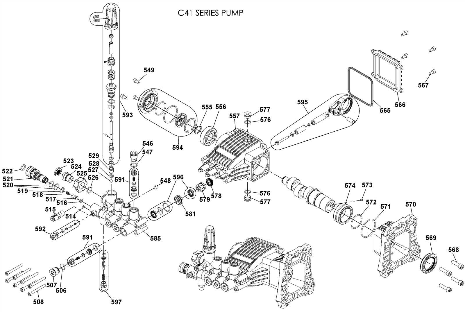
The impeller blade’s primary task is to generate rotational force. This action causes the materials to be lifted and thrown outward through the exit chute. Its design allows for efficient airflow, which helps maintain the system’s speed and ensures consistent movement without interruptions.
Key Functions of the Impeller
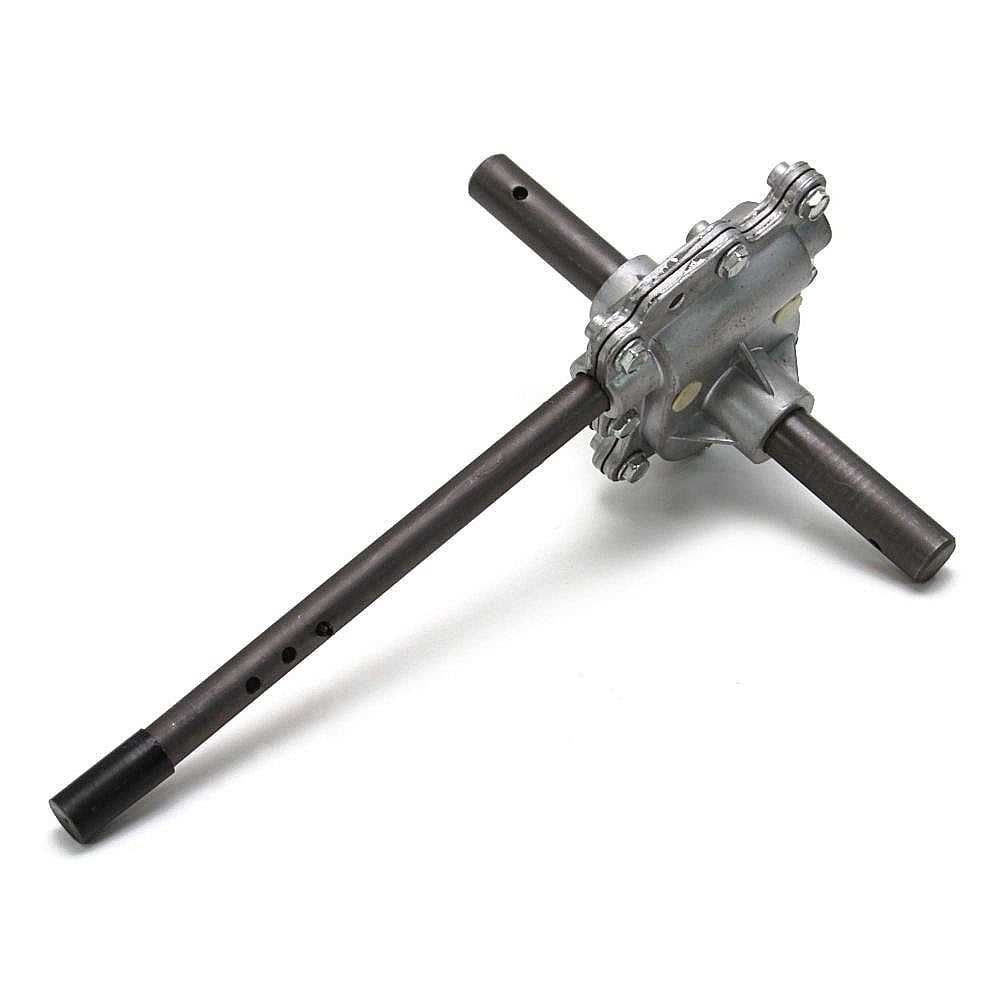
- Propelling materials
Examining the Chute Control Setup
The chute control mechanism is an essential feature that allows for the precise direction of ejected materials. Understanding its configuration helps ensure efficient operation, especially in varying conditions. By examining this system, one can gain insights into how to make adjustments that maximize functionality and control.
Key Components of the Chute Control
Several elements make up the chute control system, each playing a specific role in directing material flow. These include the lever or handle, cable assembly, and the chute itself. Together, these components work in harmony to provide smooth adjustments for the direction and distance of discharge.
Troubleshooting the Chute Mechanism
Over
Engine Parts and Their Functions
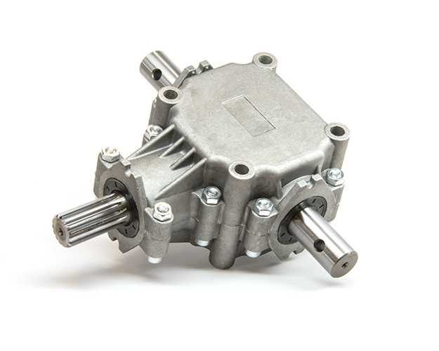
The performance and efficiency of a machine are heavily influenced by its engine components. Each element plays a vital role in ensuring smooth operation, contributing to the overall functionality and reliability of the equipment. Understanding these components helps users maintain optimal performance.
Component Function Cylinder Houses the piston and facilitates combustion for power generation. Piston Moves up and down within the cylinder, converting fuel energy into mechanical work. Crankshaft Transforms the linear motion of the piston into rotational motion, driving the output. Camshaft Controls the opening and closing of the intake and exhaust valves, regulating airflow. Valves Allow fuel-air mixture to enter the cylinder and exhaust gases to exit after combustion. Fuel Injector Sprays fuel into the combustion chamber for efficient mixing with air. Ignition System Provides the spark necessary to ignite the fuel-air mixture, initiating combustion. The Role of Shear Pins in Protection
Shear pins serve a crucial function in safeguarding machinery by preventing damage during overload situations. These components are designed to break under excessive stress, thereby absorbing impact and protecting more vital parts from failure. This mechanism is essential in maintaining the overall integrity and longevity of equipment.
When faced with resistance, shear pins act as a weak link, ensuring that more robust components remain intact. By sacrificing themselves, they mitigate the risk of costly repairs and operational downtime. This protective feature is particularly important in applications where unexpected obstacles may be encountered.
In addition to their protective role, shear pins contribute to the smooth operation of machinery. They allow for a controlled release of energy, enabling equipment to function effectively without incurring damage. Regular inspection and timely replacement of these pins are vital to ensure optimal performance and safety in operations.
Transmission Components Breakdown
This section provides an overview of the various elements involved in the transmission system of a specific equipment type. Understanding these components is crucial for maintaining optimal performance and ensuring longevity.
Key Elements of the Transmission
The transmission system is composed of several critical parts that work in unison. These include gears, shafts, and clutches, each playing a vital role in transferring power effectively. Proper functioning of these elements ensures smooth operation and efficient power delivery.
Maintenance and Care
Regular inspection and maintenance of the transmission components are essential for preventing wear and tear. Lubrication is a key factor in this process, as it helps reduce friction and prolongs the lifespan of the parts. Timely replacements of any worn-out components can significantly enhance the overall performance and reliability of the equipment.
Identifying Belt and Pulley Systems
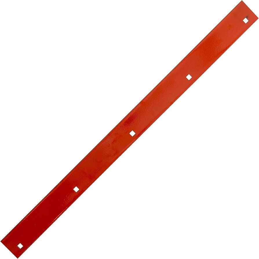
The belt and pulley mechanisms play a crucial role in transferring power within various machines. Understanding their configuration is essential for efficient operation and maintenance. These systems are designed to facilitate the movement of energy from one component to another, often impacting the overall functionality of the equipment.
When examining these assemblies, it’s important to recognize the different types of belts, such as flat or V-shaped varieties, as well as the corresponding pulleys that guide their movement. Identifying wear and tension levels is vital to ensure optimal performance, as imbalances can lead to operational inefficiencies or even damage to the machinery.
Additionally, noting the arrangement of the pulleys is essential. This includes their sizes, orientations, and the routes that the belts take through the system. Proper alignment is crucial for effective energy transfer and can significantly influence the longevity of the components involved.
Exploring the Gearbox Configuration
The gearbox serves as a crucial component in various machinery, facilitating the transmission of power from the engine to the working parts. Understanding its configuration is essential for efficient operation and maintenance. This section delves into the intricate design and functionality of the gearbox, highlighting its role in optimizing performance.
Central to the mechanism is the arrangement of gears that work together to adjust torque and speed. The interaction between these elements determines how effectively the machine can handle various tasks. Each gear serves a specific purpose, contributing to the overall efficiency of the system.
Moreover, attention to detail in the assembly and alignment of the gearbox is vital. Misalignment can lead to increased wear and tear, ultimately affecting the longevity of the machinery. Regular inspection and maintenance of these components ensure smooth operation and prevent potential breakdowns.
Troubleshooting Common Snowblower Issues
Experiencing difficulties with your snow-clearing equipment can be frustrating, but identifying and resolving these challenges can enhance performance and extend the lifespan of the machine. Common complications often arise from mechanical failures, improper maintenance, or user error. By understanding typical problems, users can implement effective solutions and ensure their equipment operates efficiently.
Identifying Common Problems
Several issues may hinder functionality. These can include starting difficulties, inadequate clearing performance, or unusual noises during operation. Recognizing the signs can lead to quicker resolutions.
Solutions and Maintenance Tips
Regular maintenance is crucial for optimal performance. Below are some solutions to common issues:
Issue Possible Cause Recommended Solution Won’t start Fuel issues or battery failure Check fuel level and battery charge; replace if necessary. Poor clearing ability Clogged auger or improper speed settings Clear any blockages and adjust speed settings as needed. Strange noises Loose parts or worn bearings Tighten loose components and replace worn parts promptly. Maintenance Tips for Longevity
Ensuring the extended lifespan of your equipment involves a series of essential care practices. Regular attention not only enhances performance but also prevents unexpected malfunctions. Implementing these guidelines can keep your machinery running smoothly for many seasons.
Regular Inspections
Frequent examinations of your unit are crucial. Look for signs of wear and tear, including frayed belts or loose components. Identifying issues early can save time and costly repairs down the line.
Proper Storage
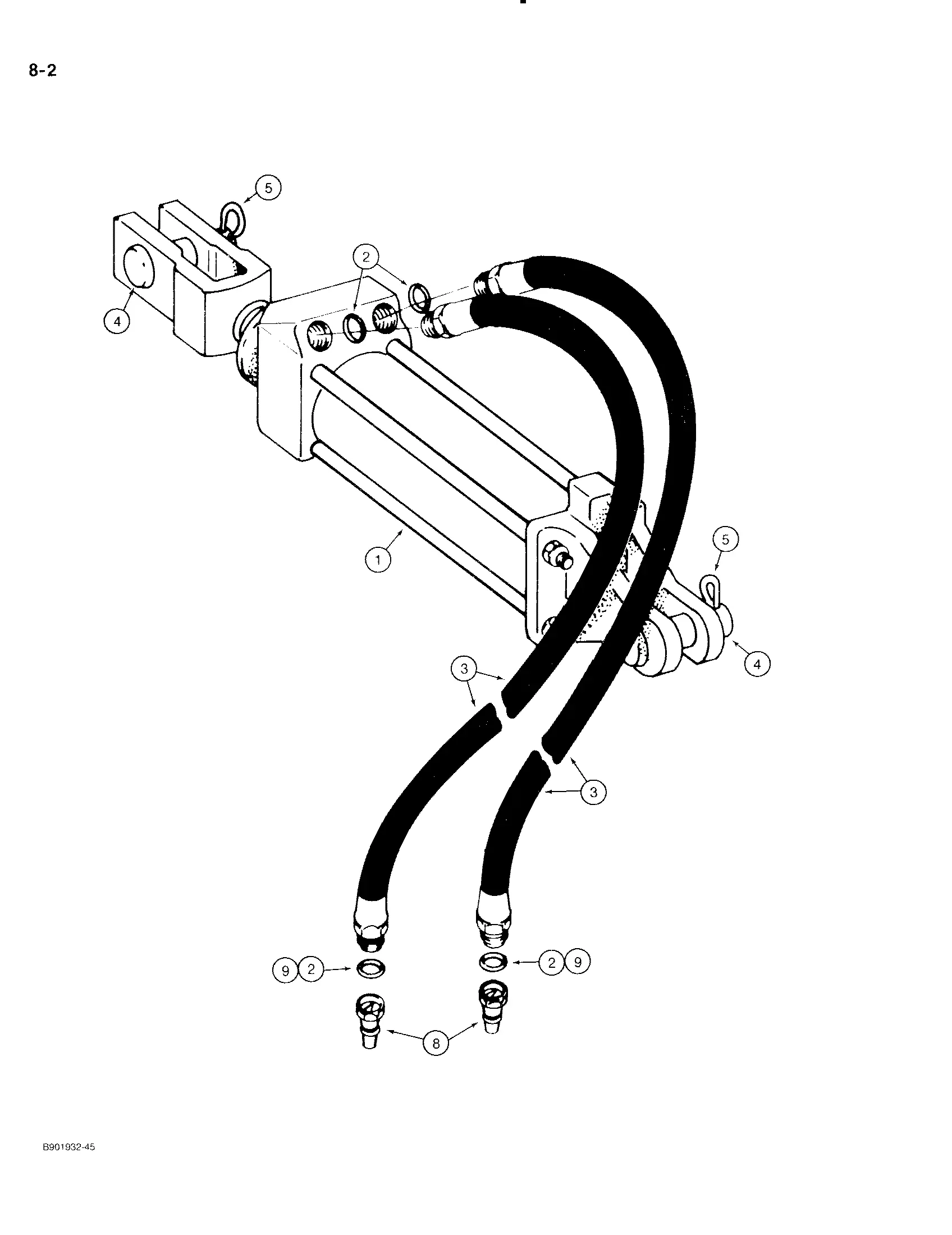
Storing your equipment correctly during off-seasons can significantly impact its longevity. Keep it in a dry, sheltered space to protect it from moisture and extreme temperatures. Additionally, consider covering it to prevent dust accumulation and potential rust.