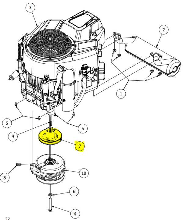
Understanding how different components interact in a mechanical system is essential for ensuring optimal performance and maintenance. By identifying key connections and functionalities, one can effectively troubleshoot and enhance the operation of such systems.
In this guide, we will delve into the structure of this powerful mechanism, uncovering the purpose of each element within the assembly. By mapping out these vital components, you will gain insight into how they contribute to the overall functionality and efficiency of the machine.
This exploration aims to simplify the complex arrangement of the system, helping you navigate through its intricate setup. Whether for maintenance or improvement, having a clear understanding of how each piece operates is invaluable.
HP Engine Components Overview
The high-performance mechanical system in focus operates through a combination of interconnected elements, each playing a critical role in the overall functionality. Understanding the distinct components and their purposes helps optimize the system’s operation and longevity. Below is a closer look at the essential mechanical elements that contribute to this power source.
Key Mechanical Elements
- Power Unit: The central mechanism that generates motion, converting stored energy into usable mechanical power.
- Fuel System: Supplies the necessary energy to the power unit, ensuring efficient combustion and performance.
- Cooling Mechanism: Regulates temperature, preventing overheating and maintaining optimal operating conditions.
- Ignition System: Initiates the combustion process, ensuring smooth and reliable start-up.
- Exhaust Setup: Channels out gases produced during operation, maintaining proper airflow and environmental standards.
Maintenance Considerations

- Regular inspection and cleaning of the fuel
Main Sections of the Engine Block
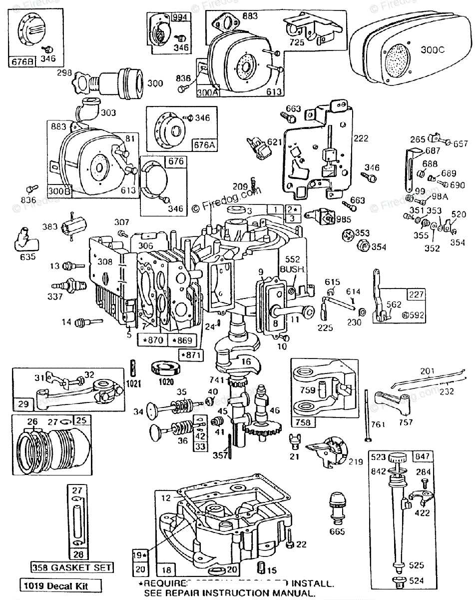
The core structure that drives mechanical processes consists of multiple interconnected components. Each segment plays a crucial role in ensuring efficient power generation and smooth operation. These sections form the foundation for converting energy into motion, making the entire mechanism function seamlessly.
- Crankcase: This is the lower portion that houses the rotating assembly and provides a base for supporting other elements.
- Cylinder Head: Positioned at the top, this section seals the combustion chamber and helps manage the air-fuel mixture.
- Piston and Connecting Rods: These moving parts transfer energy from combustion, driving the rotary motion.
- Valves and Timing Mechanism: These components control the intake of air and fuel, as well as the release of exhaust gases, ensuring proper synchronization during operation.
Crankshaft and Its Associated Parts
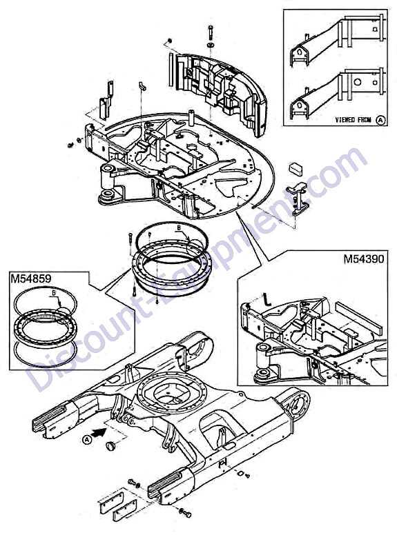
The rotating mechanism plays a crucial role in ensuring the smooth conversion of linear motion into rotational force. This core element is essential in driving other key components, helping to maintain balance and efficiency throughout the entire mechanical system.
Main Elements of the Crankshaft Assembly
Several interconnected components work together to support the rotation and power transmission. These include various couplings, fasteners, and counterweights that are strategically placed to enhance functionality.
Component Description Connecting Rod Links the reciprocating motion to the rotational axis, transferring force. Bearings Provides support for the rotating shaft, reducing friction and wear. Counterweights Understanding the Valve Mechanism Layout
The arrangement of components within the valve system plays a critical role in the overall operation of a mechanical device. This layout ensures the controlled movement of key elements, allowing the system to function efficiently and reliably. Proper alignment and positioning of these parts are essential for optimal performance, ensuring smooth transitions between different operational phases.
Valve placement and its interaction with adjacent components define the effectiveness of the mechanism. The structure includes intricate elements that manage the flow of gases, regulate timing, and control the opening and closing cycles. Without precise organization, the system may fail to deliver the necessary output.
Key to understanding this layout is recognizing how various elements collaborate within a confined space. By mastering the configuration, one can maintain, troubleshoot, and optimize the performance of the device.
Air Filter Housing and Connections
The enclosure surrounding the air intake system plays a vital role in ensuring that clean airflow reaches critical internal components. The connections within this system ensure the proper attachment and functionality of each part, contributing to the overall performance and efficiency of the equipment.
Here are key components of the air filtration system:
- Housing unit: The protective casing that shields the filtration element from external debris and contaminants.
- Air filter: The core component responsible for trapping dust and particles, ensuring only purified air flows into the machine.
- Connecting seals: These maintain airtight connections between the housing and adjacent sections, preventing unfiltered air from entering.
- Mounting brackets: Structural supports that securely hold the enclosure in place, reducing vibrations and ensuring stability during operation.
The careful
Fuel System Structure and Components
The fuel delivery mechanism plays a crucial role in the overall functionality of a power unit. Its design encompasses various elements that work in harmony to ensure a consistent and efficient supply of combustible material. Understanding this intricate network is essential for maintaining optimal performance and reliability.
Key components of this system include the fuel tank, pump, filter, and carburetor, each serving a specific function in the process of fuel management. The fuel tank stores the liquid, while the pump transports it to the necessary points. A filter is implemented to remove impurities, ensuring that only clean fuel reaches the carburetor, where it is mixed with air to create a combustible mixture. This precise interaction of elements highlights the importance of regular inspection and maintenance to prevent operational issues.
Moreover, understanding the layout of these components is vital for troubleshooting potential problems. Familiarity with the connections and functions of each part allows for efficient repairs and replacements, ultimately enhancing the longevity of the machine.
Ignition Coil and Wiring Diagram
The ignition coil plays a crucial role in the starting system of small machinery, converting low voltage from the battery into a high voltage required for spark generation. This component ensures the proper ignition of the fuel-air mixture, enabling the machine to function efficiently. Understanding its configuration and connections is essential for effective troubleshooting and maintenance.
Functionality of the Ignition Coil
The primary purpose of the ignition coil is to generate a high-voltage spark at the right moment. This process involves:
- Transforming the battery’s low voltage into a high voltage.
- Sending the generated spark to the spark plug for combustion initiation.
- Ensuring the timing of the spark aligns with the engine’s operational cycle.
Wiring Connections Overview
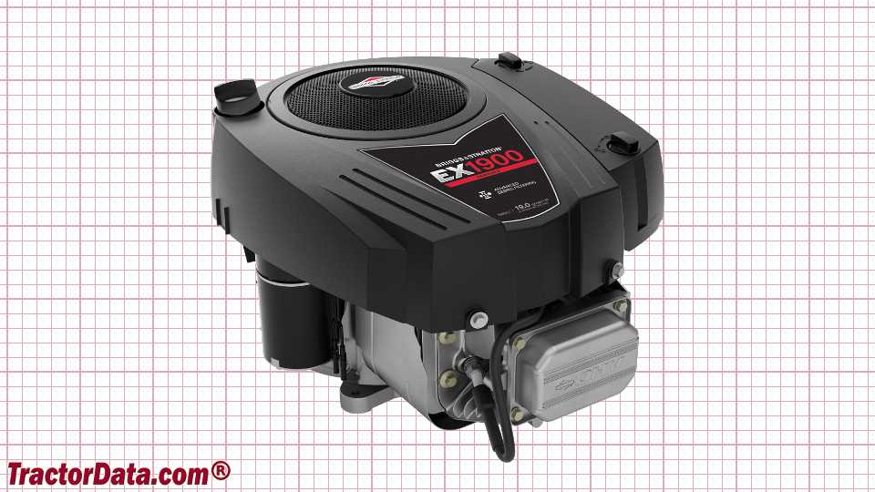
Correct wiring is vital for the ignition coil’s performance. The following points outline the key wiring connections:
- The positive terminal connects to the battery voltage source.
- The negative terminal connects to the ignition switch.
- A wire runs from the ignition coil to the spark plug, delivering the generated spark.
Proper understanding of the ignition coil and its wiring can greatly enhance maintenance efforts, ensuring reliable operation of the machinery.
Starter Motor Assembly Breakdown
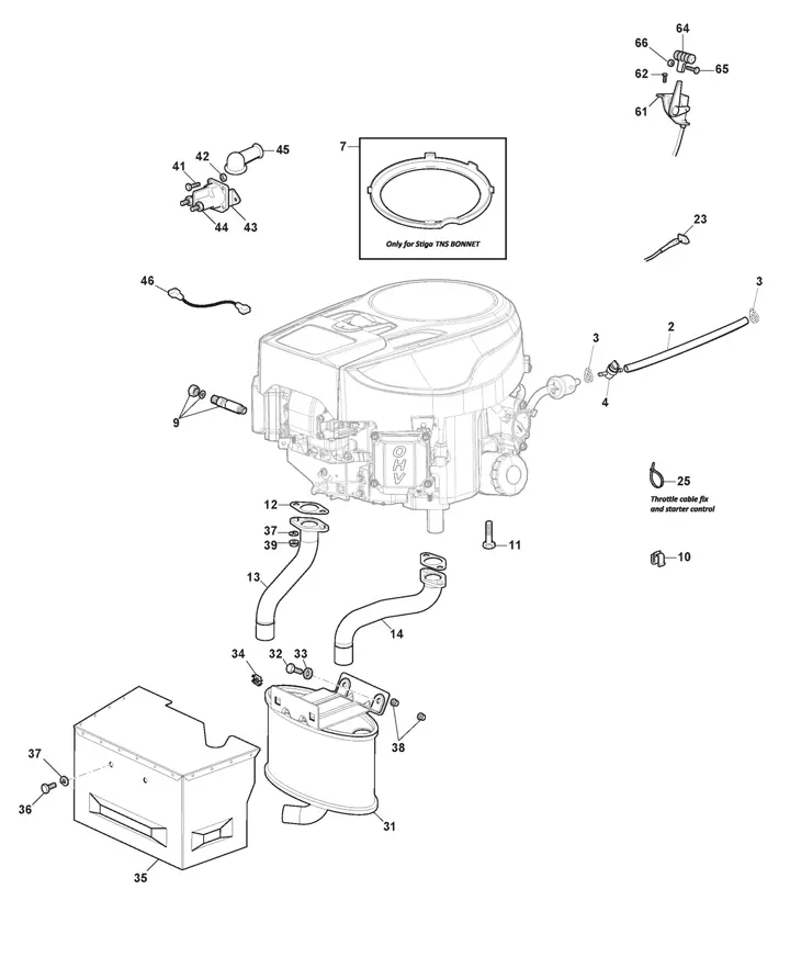
The starter motor is a crucial component responsible for initiating the operation of a power unit. Understanding its assembly is essential for effective maintenance and repair. This section delves into the intricate details of the starter motor assembly, highlighting its various components and their functions.
Components of the Starter Motor
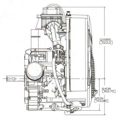
The starter motor assembly consists of several key elements that work together to facilitate smooth operation. These include:
- Motor Housing: The outer casing that protects the internal components.
- Armature: A rotating part that interacts with the magnetic field to generate motion.
- Solenoid: An electromechanical switch that engages the starter motor when the ignition is activated.
- Commutator: A device that helps convert the alternating current produced in the armature into direct current.
Understanding the Functionality
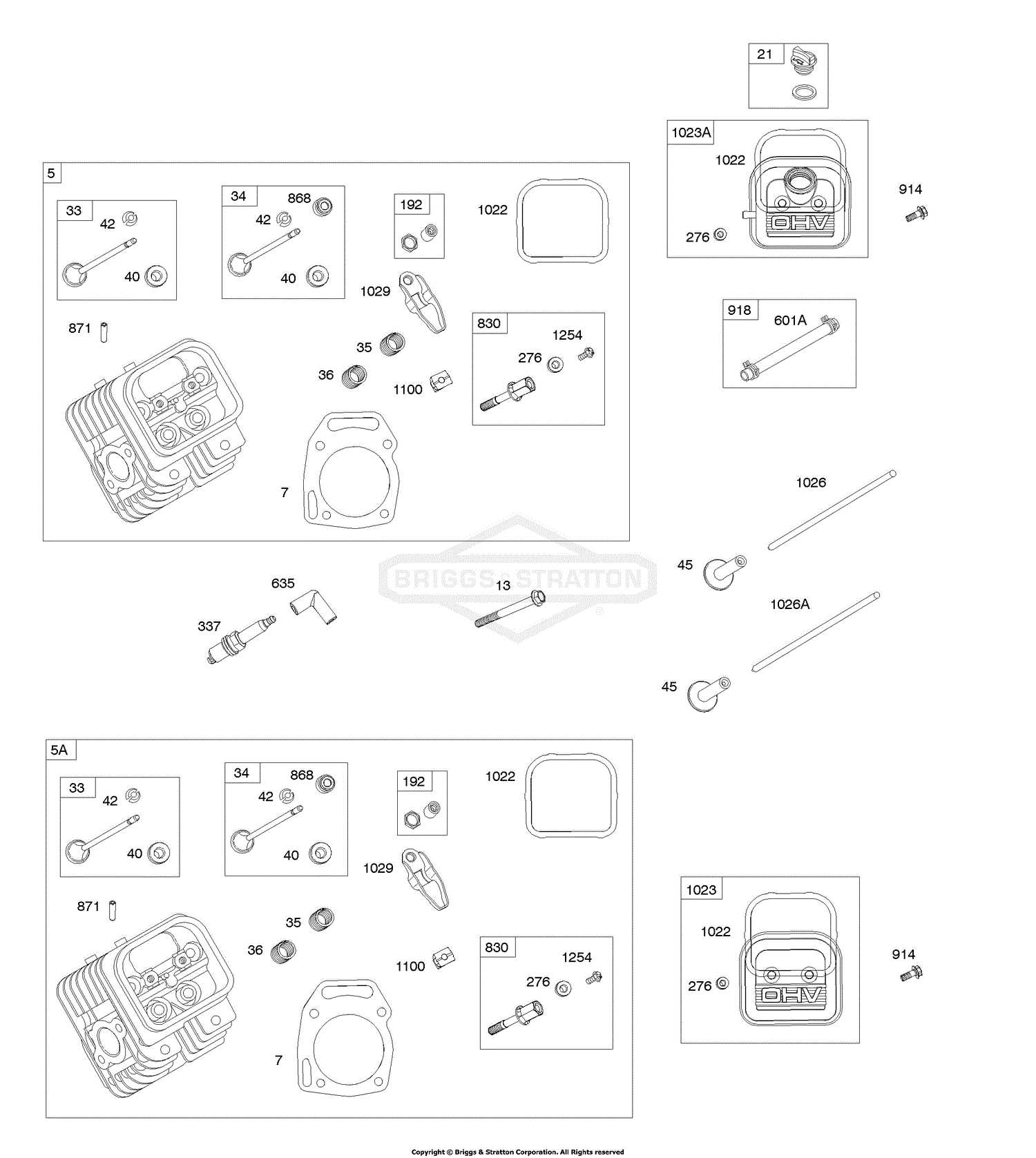
Each component plays a vital role in the functionality of the starter motor. When the ignition is turned on, the solenoid is activated, allowing current to flow to the motor. This action engages the armature, which then begins to rotate. The commutator ensures that the electrical flow is directed properly, allowing the motor to function efficiently. Regular inspection and maintenance of these components can prevent potential failures and extend the lifespan of the assembly.
Exhaust System Components Explained
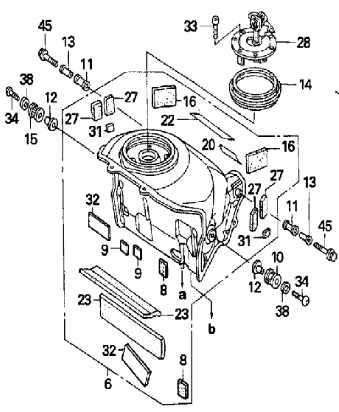
The exhaust system plays a crucial role in the overall performance and efficiency of a mechanical apparatus. Its primary function is to channel the byproducts of combustion away from the core mechanisms, ensuring optimal operation and minimizing harmful emissions. Understanding the various elements within this system is essential for maintenance and troubleshooting.
Key components include the muffler, which reduces noise generated during operation, and the exhaust manifold, responsible for collecting gases from multiple cylinders and directing them to the muffler. Another important part is the tailpipe, which safely expels the processed gases into the atmosphere. Proper functioning of these elements is vital for maintaining performance and compliance with environmental standards.
Regular inspection of the exhaust system can prevent issues such as leaks or blockages, which may lead to decreased efficiency or increased emissions. Keeping this system in good condition ensures that the apparatus operates smoothly and safely.
Oil Filter and Lubrication Pathways
Effective maintenance of machinery relies on the proper management of fluids, particularly oil, which plays a crucial role in ensuring smooth operation and longevity. The oil filtration system is designed to remove contaminants, while the pathways facilitate the distribution of lubricants throughout various components. Understanding these systems is essential for optimal performance and prevention of premature wear.
At the heart of the lubrication process lies the oil filter, which performs several vital functions:
- Contaminant Removal: It traps dirt, debris, and other impurities that could harm the mechanical parts.
- Fluid Circulation: Maintains a continuous flow of clean oil to vital areas, ensuring adequate lubrication.
- Pressure Regulation: Helps maintain the necessary oil pressure for optimal functionality.
The lubrication pathways are intricately designed to ensure that oil reaches all necessary components efficiently:
- Oil Pump: Initiates the flow of oil from the reservoir to the filter and various parts.
- Channels: Guide the oil to different sections, such as bearings and cylinders, where lubrication is critical.
- Return Lines: Allow used oil to return to the reservoir for recycling and re-filtering.
Maintaining the oil filter and understanding the lubrication pathways are paramount for achieving optimal efficiency and extending the lifespan of the machinery.
Carburetor and Throttle Linkage Overview
The carburetor plays a crucial role in the functionality of a small power unit, controlling the mixture of air and fuel that powers the system. Its efficiency directly impacts the overall performance, making it vital for optimal operation.
Throttle linkage serves as a connection between the accelerator mechanism and the carburetor, regulating the amount of fuel-air mixture entering the combustion chamber. This component ensures smooth transitions in speed and enhances responsiveness during operation.
Understanding the relationship between the fuel delivery system and the throttle mechanism is essential for troubleshooting performance issues. Regular maintenance of these components can prevent potential problems and ensure a smooth operation.
Cooling System Elements and Placement

The efficiency of any mechanical apparatus significantly relies on its temperature management system. This section delves into the various components responsible for regulating heat within the machine, ensuring optimal performance and longevity. Understanding the arrangement of these elements is crucial for effective maintenance and troubleshooting.
Component Description Placement Cooling Fan Helps circulate air around the apparatus to dissipate heat. Mounted on the flywheel for direct airflow. Heat Exchanger Transfers heat away from the working parts to the surrounding air. Located adjacent to the combustion chamber. Cooling Fins Increase surface area for enhanced heat dissipation. Attached to the exterior of the housing. Air Ducts Guide airflow to critical components needing cooling. Integrated within the frame for efficient airflow management. Flywheel and Magneto Assembly Guide
The flywheel and magneto assembly plays a crucial role in the functioning of small machinery, serving as the core component that generates electrical energy while ensuring smooth operation. Understanding the assembly’s structure and functionality is essential for maintaining performance and achieving optimal results.
Understanding the Components
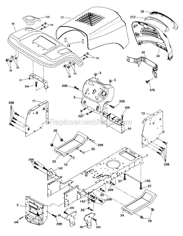
The assembly consists of two primary elements: the flywheel and the magneto. The flywheel, typically made of metal, acts as a rotational mass, stabilizing the engine’s speed during operation. In contrast, the magneto is an electrical device responsible for producing spark energy necessary for ignition. Together, these components ensure efficient combustion and reliable performance.
Assembly and Maintenance Tips
When assembling the flywheel and magneto, it is vital to ensure proper alignment to avoid operational issues. Start by securely attaching the magneto to its designated location, followed by carefully positioning the flywheel. Regular maintenance, including checking for wear and tear, is essential to prolong the lifespan of these components. Additionally, always refer to the manufacturer’s guidelines for specific torque specifications and procedures.