When it comes to high-performance engines, recognizing the different mechanical elements is essential for both maintenance and repair. Whether you’re dealing with minor fixes or significant replacements, knowing how the various elements interact ensures the engine functions smoothly and efficiently over time.
In this section, we’ll explore the crucial components of a robust engine, focusing on how each part plays a vital role in overall functionality. Identifying these elements and understanding their purpose will help keep the machine in excellent working condition. Proper care and regular upkeep are essential to maintain the engine’s optimal performance and longevity.
By reviewing the structure and operation of the essential elements, you can
Overview of the Vanguard 35 HP Engine
The 35-horsepower engine is known for its reliable performance and is often chosen for demanding applications. Its design allows for efficient operation in various conditions, ensuring durability and strength over extended use. This motor is particularly appreciated for its balance between power output and fuel efficiency, making it suitable for both heavy-duty tasks and lighter operations.
Key Features of the Engine
One of the engine’s standout characteristics is its ability to handle high workloads while maintaining stability. This model is equipped with advanced cooling systems that help to prevent overheating during prolonged use, and its robust build reduces the likelihood of frequent maintenance needs.
Applications and Usability
Designed to meet the needs of professionals and hobby
Main Components of the 35 HP Vanguard

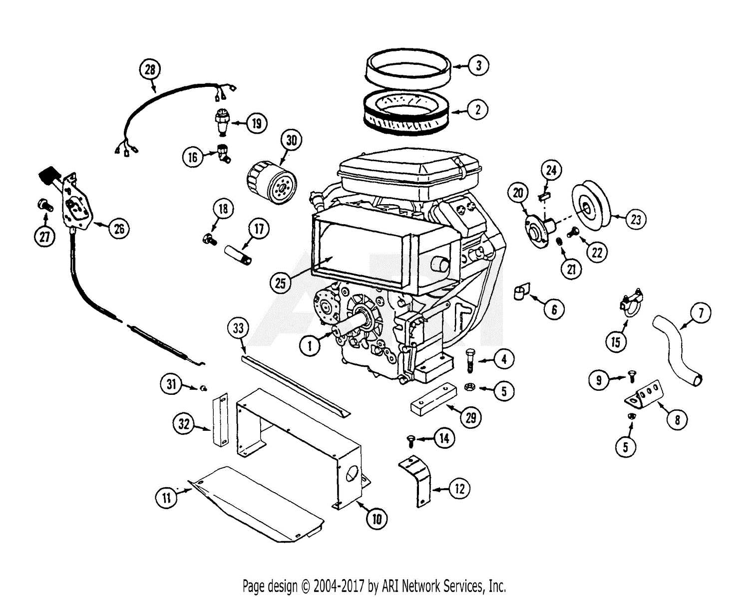
The 35 HP engine is built with several critical elements that work together to ensure reliable performance. Understanding these components is essential for maintaining the motor and ensuring it functions at its best. Below, we explore the key features that contribute to its robust operation.
Engine Block
The heart of the motor, the engine block, houses the main working parts such as the cylinders. Its durability is vital for supporting the entire structure, and it’s designed to withstand high pressures and temperatures during operation.
Fuel and Air Systems
The power unit relies on a precise balance of fuel and air. The fuel system regulates the flow, ensuring efficient combustion, while the air intake system controls the oxygen needed for optimal power output. Together, they ensure smooth and efficient operation.
How to Identify Engine Components
Recognizing different elements within an engine can be essential for proper maintenance and repair. Understanding the core elements of a motor helps ensure that each piece functions correctly, contributing to the overall performance of the machine.
Key Components to Focus On
When examining a motor, focus on prominent areas such as the cylinder, crankshaft, and valve system. These elements are often easy to identify based on their location and size, playing crucial roles in power generation and movement.
Visual Cues and Labeling
Many engine parts come with visual identifiers, like serial numbers or distinctive shapes, which can help distinguish them. Familiarizing yourself with these markers makes the identification process faster and more accurate.
Detailed Breakdown of the Engine System
The engine structure is a complex yet well-designed mechanism, where every component plays a critical role in ensuring smooth operation. Understanding how different elements work together can help in maintaining the system and troubleshooting any issues. This section will explore the key segments of the system and their respective roles in performance optimization.
Main Components and Their Roles
The primary components are responsible for delivering power efficiently. These include the power generation unit, fuel delivery, and cooling systems. Each of these segments is vital for ensuring long-lasting performance and reliability.
Key Interconnections
The interaction between various parts is crucial for balanced engine operation. The fuel system ensures proper energy flow, while the cooling mechanism prevents overheating. All of these processes are intricately linked to maintain optimal function.
| Component | Function |
|---|---|
| Power Unit | Ge
Understanding the Fuel System Layout
The fuel system is an essential component in ensuring smooth engine operation, efficiently delivering fuel from the tank to the combustion chamber. To maintain proper performance, it’s important to grasp how the different parts of this system interact and contribute to overall functionality. Key Components of the Fuel System
Cooling and Exhaust Parts ConfigurationThis section provides an overview of the essential components involved in the temperature regulation and gas release systems of high-performance engines. Understanding these elements is crucial for maintaining optimal functionality and ensuring longevity. Effective cooling mechanisms are vital to prevent overheating, while exhaust configurations play a key role in optimizing engine performance. Here are the primary elements associated with these systems:
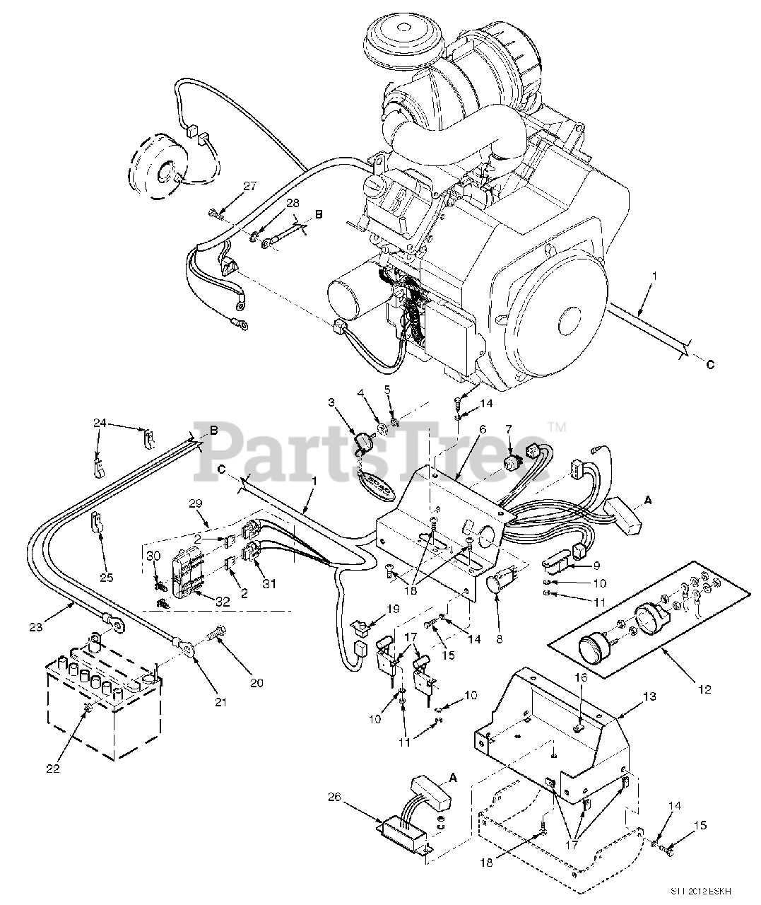
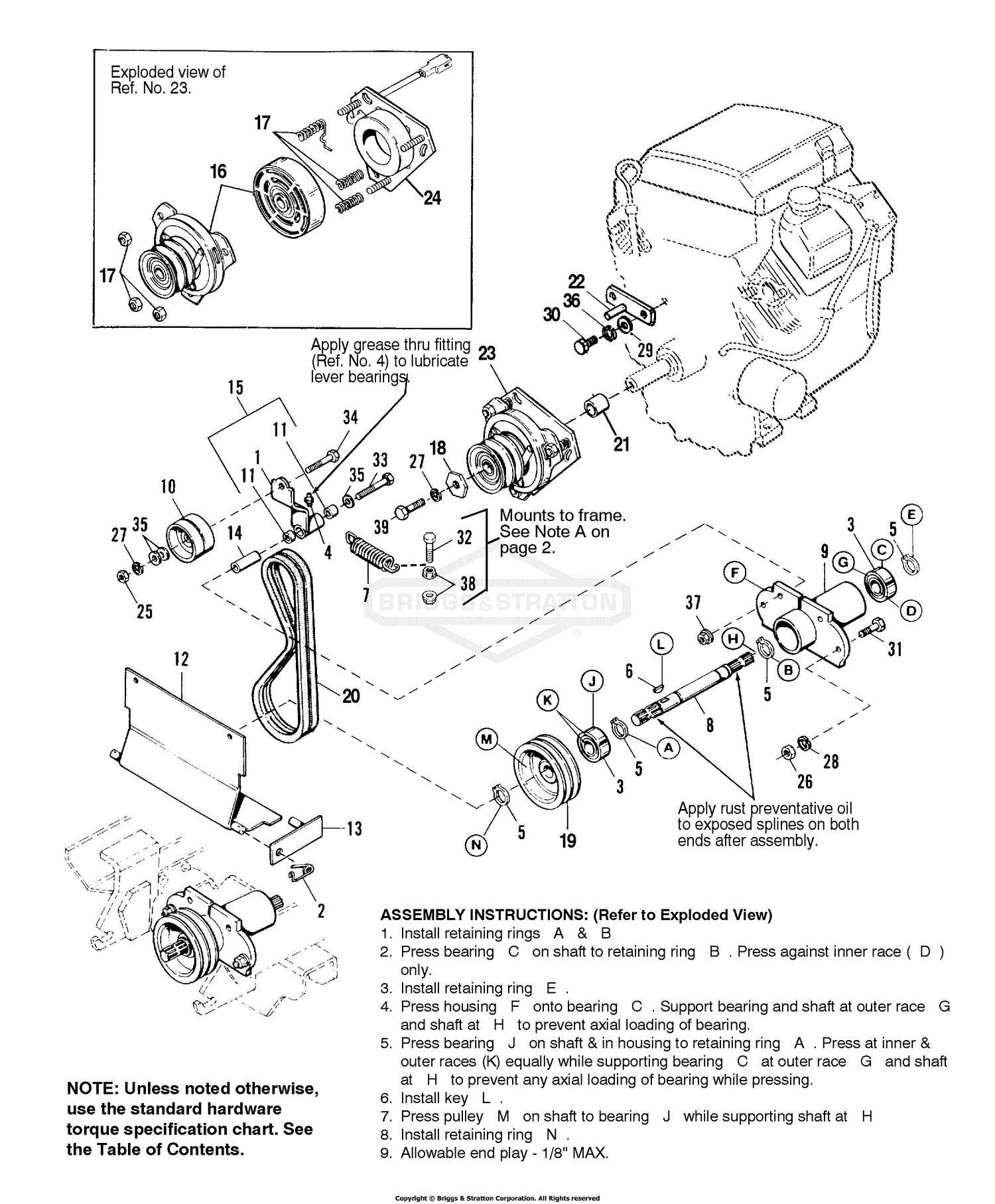
Proper installation and maintenance of these components are crucial for achieving peak performance. Regular checks and timely replacements can prevent potential issues and enhance the overall efficiency of the engine. Electrical Components and Wiring DiagramThis section provides an overview of the vital electrical elements and their connections within the engine system. Understanding these components is essential for troubleshooting and maintenance, ensuring optimal performance and longevity. Key Elements: The electrical setup consists of several crucial parts, including the ignition coil, battery, starter motor, and various sensors. Each component plays a specific role in the operation of the engine, contributing to efficient functionality. Wiring Overview: The wiring network facilitates communication between the components, enabling the engine to function smoothly. Proper wiring ensures that power is efficiently distributed, minimizing the risk of faults and enhancing reliability. Drive System Components and AssemblyThe drive system of a power unit is crucial for ensuring efficient performance and effective power transmission. This section explores the key elements involved in the assembly and functioning of the drive mechanism, highlighting their roles and interconnections. Essential ElementsSeveral components work in harmony to create a functional drive system. Understanding these parts is essential for proper maintenance and troubleshooting. The following are the primary components:
Assembly ProcessProper assembly of the drive system is vital for optimal operation. Here are the steps involved in the assembly:
Maintenance Tips for Key Engine PartsProper upkeep of essential components is vital for ensuring optimal performance and longevity of the machinery. Regular maintenance not only enhances efficiency but also helps in identifying potential issues before they escalate. By focusing on key areas, operators can achieve a reliable operation and reduce the risk of unexpected failures. Regular Inspection and CleaningRoutine examination of critical engine elements is crucial. Keeping these components clean from debris and buildup can significantly improve functionality. Ensure that air filters are checked and cleaned or replaced as necessary. A clean filter allows for better airflow, promoting a more efficient combustion process. Lubrication and Fluid ChecksMaintaining appropriate levels of lubrication is essential for reducing friction and wear on moving parts. Regularly check oil levels and quality; replace it according to the manufacturer’s recommendations. Additionally, monitor coolant levels to prevent overheating, which can lead to serious damage. Replacement Guidelines for Worn PartsMaintaining the efficiency of machinery requires regular inspection and timely replacement of damaged or worn components. Adhering to appropriate guidelines ensures optimal performance and longevity of the equipment. When addressing the need for replacements, consider the following steps:
By following these guidelines, operators can effectively manage the replacement of worn components, leading to improved functionality and reduced downtime. |
