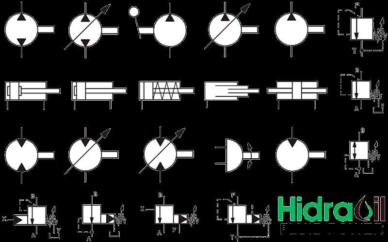
The intricate design of advanced drive systems plays a crucial role in enhancing the efficiency and performance of various applications. Each element within these systems contributes to their overall functionality, creating a seamless integration that ensures optimal operation. A detailed exploration of these components reveals their significance and the intricate relationships they share.
In this section, we will delve into the specific elements that make up these sophisticated mechanisms. By examining their configurations and interconnections, we can gain valuable insights into how they function collectively. Understanding these intricacies is essential for both maintenance and innovation in the field.
Through a thorough analysis, we aim to provide clarity on the various units involved. This knowledge not only aids in troubleshooting and repairs but also fosters a deeper appreciation for the engineering behind these systems. Join us as we uncover the essential features that drive performance and reliability in advanced applications.
Parker Wheel Motor Overview
This section provides a comprehensive insight into a specialized hydraulic device designed for efficient energy transfer. Its innovative design ensures optimal performance in various applications, enhancing productivity and reliability in demanding environments.
Key Features
The advanced mechanism offers superior torque and speed control, making it suitable for heavy-duty tasks. Its robust construction ensures longevity, while precision engineering minimizes maintenance needs, allowing for seamless operation across diverse industries.
Applications
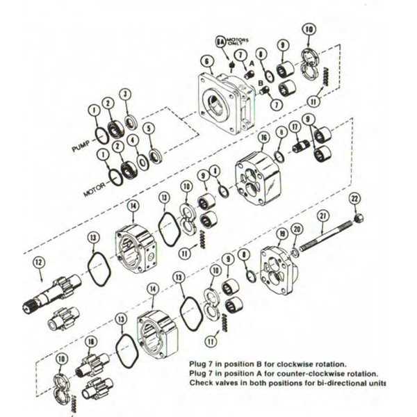
This technology finds extensive use in construction machinery, agricultural equipment, and material handling systems. Its adaptability to different operational conditions makes it an ultimate choice for professionals seeking efficiency and power in their projects.
Key Components of Wheel Motors
Understanding the essential elements that comprise these innovative systems is crucial for effective application and maintenance. Each component plays a vital role in ensuring optimal performance and efficiency, contributing to the overall functionality of the assembly.
Drive Mechanism
The drive mechanism is fundamental to the operation of the system, converting energy into rotational movement. This component is typically designed to withstand significant torque while ensuring smooth transmission. Advanced designs often incorporate features to enhance durability and minimize wear, which is essential for prolonged usage.
Control Unit
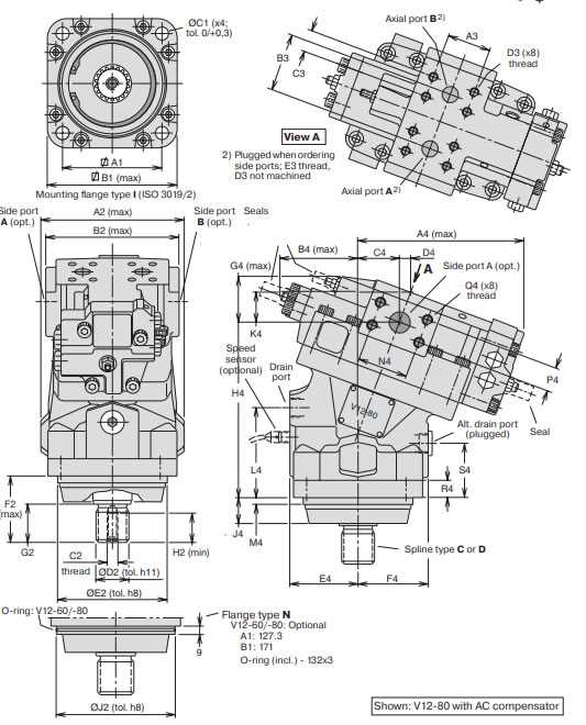
The control unit acts as the brain of the system, managing various functions such as speed regulation and torque adjustment. This element allows for precise manipulation of performance parameters, ensuring that the assembly responds effectively to operator inputs. Enhanced control algorithms can significantly improve efficiency and adaptability to different operating conditions.
In summary, a thorough grasp of these critical components is essential for anyone involved in the design, maintenance, or operation of these advanced assemblies. Understanding their interconnections and functionalities can lead to improved performance and longevity of the system.
Understanding Motor Diagrams
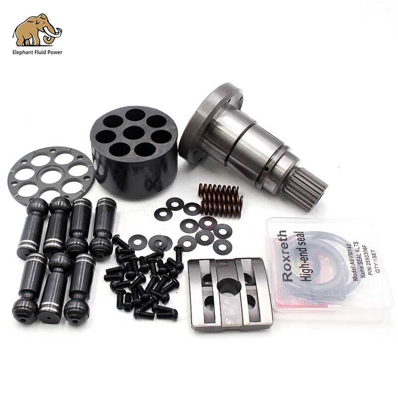
Comprehending visual representations of mechanical components is crucial for effective maintenance and troubleshooting. These illustrations provide insights into the arrangement and functionality of various elements, facilitating a deeper grasp of operational principles and enhancing repair efficiency.
Key Components Overview
Identifying essential elements within these illustrations helps in recognizing their roles. Each segment contributes to the overall system, ensuring smooth operation and efficiency.
| Component | Description |
|---|---|
| Housing | Enclosure that protects internal mechanisms. |
| Shaft | Rotating element that transfers motion. |
| Bearings | Support and facilitate smooth rotation. |
| Seals | Prevent leakage of fluids and contaminants. |
Interpreting Illustrations
Learning to decode these visuals enhances understanding of functionality and assembly processes. Familiarity with symbols and layouts can significantly improve diagnostic capabilities.
Types of Parker Wheel Motors
There are several models available that cater to different applications, each designed for specific mechanical and performance requirements. These units vary in their structure and functional characteristics, providing solutions for a range of operational needs. The designs are tailored for durability, efficiency, and adaptability across various equipment configurations.
High-Torque Variants: These units are built to deliver maximum force at low speeds, ideal for tasks that require substantial pushing or pulling power. Their robust construction ensures they can handle demanding conditions while maintaining smooth operation.
Compact Models: Optimized for space-limited environments, these units offer efficient performance in a smaller footprint. Despite their reduced size, they provide reliable power and are commonly used where space constraints are critical.
Speed-Oriented Designs: Focusing on high rotational speeds, these designs prioritize velocity over force, making them suitable for applications where quick motion is necessary. They strike a balance between efficiency and high-speed output.
Importance of Motor Parts Identification
Understanding the various components of a mechanical system is crucial for ensuring smooth operation, effective maintenance, and long-term reliability. Each element within the assembly serves a specific function, and recognizing these components helps streamline troubleshooting, enhance performance, and prevent unnecessary wear. Detailed knowledge of these structures allows for precise interventions when issues arise, minimizing downtime.
Efficient Maintenance
Identifying each element correctly is key to efficient maintenance routines. Accurate recognition ensures that each component is serviced according to its unique requirements, leading to improved longevity and reduced chances of malfunction. Routine checks become more streamlined, making repairs more targeted and preventing future breakdowns.
Optimized System Performance
When each element of the mechanism is correctly identified, it contributes to the overall efficiency of the system. Precise knowledge of these components supports optimization efforts, ensuring that the system operates at peak performance while reducing the risk of failure.
Common Issues with Wheel Motors
When dealing with mechanical devices designed for movement and power transmission, various operational problems can arise over time. These challenges can impact performance, efficiency, and longevity, often requiring timely attention to prevent further complications. Understanding the root causes of these issues can help ensure proper maintenance and prolong the service life of the machinery.
- Overheating: Excessive heat is a frequent problem, usually resulting from overuse, insufficient lubrication, or blocked airflow. This can lead to premature wear and reduced efficiency.
- Fluid Leaks: Leaking of hydraulic or lubricating fluids often signals damaged seals or cracks, which can result in diminished performance and even component failure if not addressed quickly.
- Excessive Noise: Unusual noises during operation may point to internal friction, loose parts, or improper alignment, all of which require immediate investigation to prevent serious damage.
- Reduced Power: Diminished output could be caused by blockages, mechanical wear, or issues in the system controlling energy distribution, leading to reduced efficiency.
Addressing these problems promptly helps maintain optimal function and prevent further degradation, ensuring reliable performance under various operating conditions.
Maintenance Tips for Parker Motors
Ensuring the longevity and efficiency of mechanical systems relies heavily on proper care and attention to detail. Regular upkeep is essential to prevent premature wear, extend service life, and avoid unexpected malfunctions. By following consistent practices, you can maintain optimal performance over time.
Regular Inspection: Periodic checks are crucial for identifying any signs of wear or potential issues. Look for loose connections, unusual noises, or irregular movements that could indicate underlying problems.
Lubrication: Keeping all moving components well-lubricated is vital to reduce friction and prevent overheating. Ensure that the appropriate lubricant is used and apply it according to the manufacturer’s recommendations.
Cleanliness: Dirt and debris can accumulate over time, affecting the smooth operation of components. Regular cleaning of external and accessible internal parts helps to keep the system running smoothly without obstructions.
Timely Replacement: Replacing worn or damaged elements at the right time can significantly improve overall performance and prevent costly repairs down the line. Always use high-quality replacement materials to ensure reliability.
Assembly Process Explained
The construction process is a critical aspect of ensuring a device functions optimally. This section outlines the detailed steps required to put together the necessary components for smooth operation, focusing on accuracy and alignment. The process involves a sequential arrangement of elements to create a fully operational system, where each part must fit into place with precision.
| Step | Description |
|---|---|
| 1 | Prepare the foundational structure by aligning the base components correctly to ensure stability for the entire system. |
| 2 | Attach intermediary sections, making sure that each segment connects securely to the adjacent part without gaps or misalignments. |
| 3 | Install the connectors and fasten the joints, ensuring that the bonding between individual components is tight and reliable. |
| 4 | Insert the rotating mechanisms, taking care to place them in the designated slots for proper alignment and functionality. |
| 5 | Finalize the assembly by securing all parts with locking elements, ensuring that the system is fully stable and ready for testing. |
By following these steps meticulously, the entire setup comes together seamlessly, ensuring the final structure performs as expected under various conditions.
Functionality of Each Component
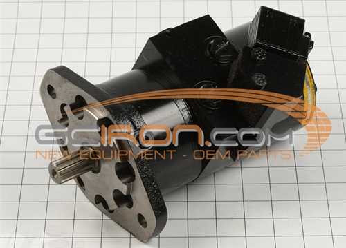
Understanding the role of each element in this system is key to maintaining its performance and efficiency. Each unit contributes to the overall functionality by performing a specific task that supports the operation of the entire assembly.
Main Structural Elements
- Core Unit: This central component serves as the foundation, ensuring stability and control over the movement and direction.
- Fluid Circulation Mechanism: Responsible for the smooth transmission of energy, this section helps in distributing power evenly across the entire system.
Additional Functional Components
- Regulator: Adjusts the flow and pressure, maintaining consistent performance under varying conditions.
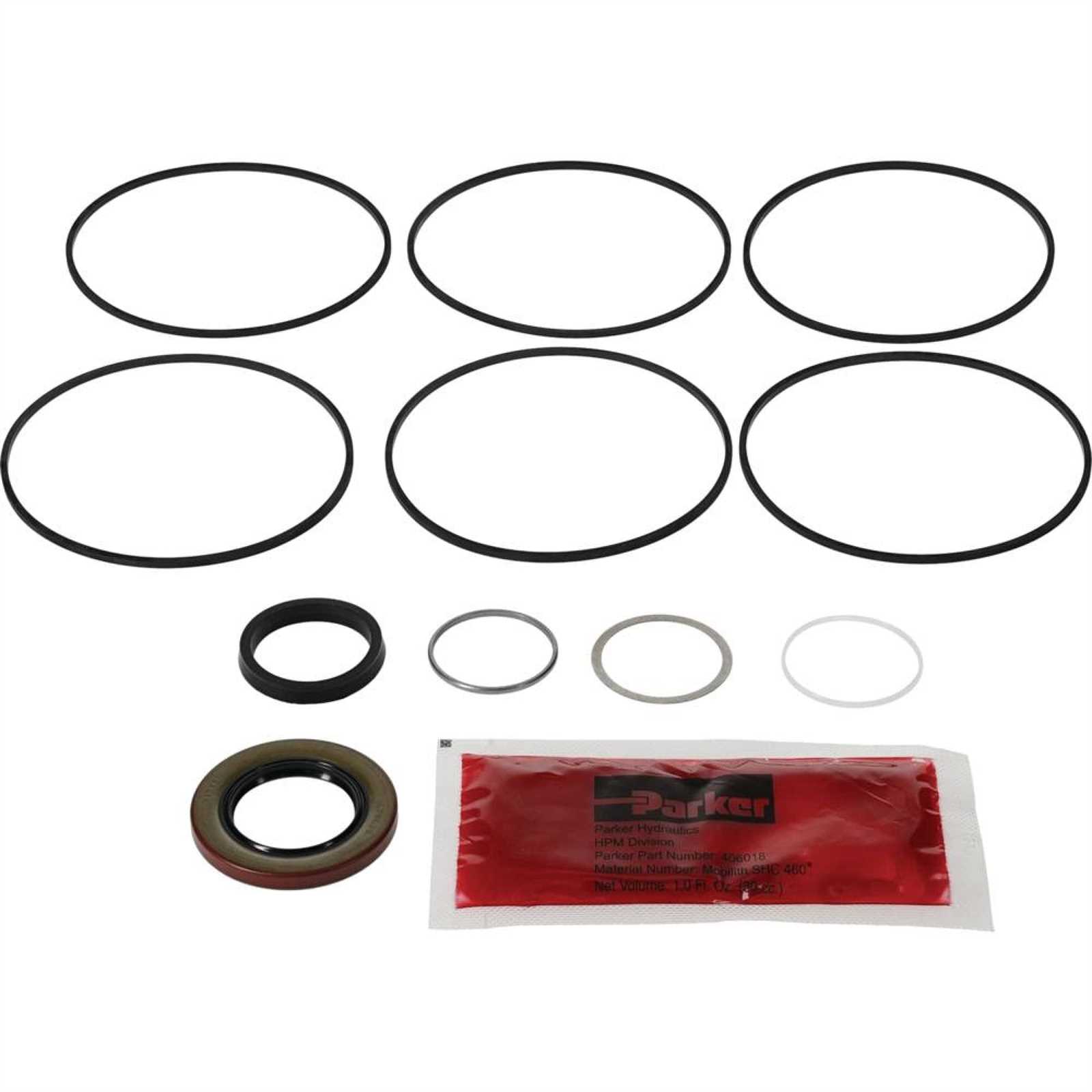
- Sealing Units: Prevent unwanted leaks and ensure the system remains sealed, protecting it from external damage.
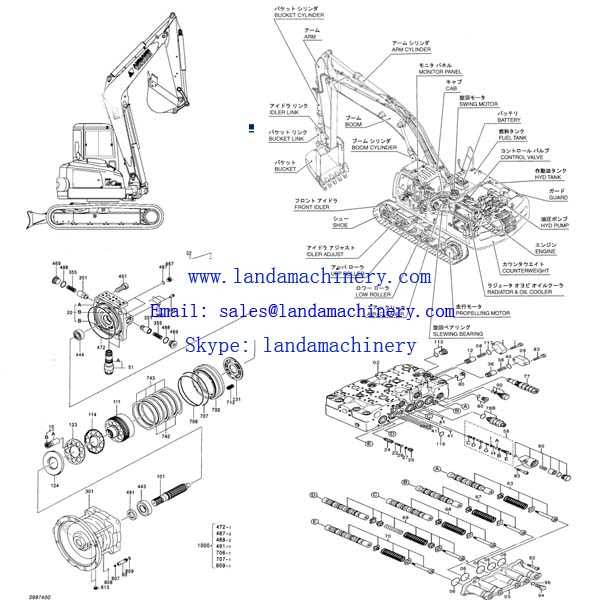
How to Read Motor Diagrams
Understanding the layout of mechanical and electrical schematics is essential for identifying key elements and connections. These visual tools offer a comprehensive view of the system, allowing users to grasp how each component functions within a broader assembly.
Key Elements to Focus On
- Symbols: Each component in a diagram is represented by a specific icon. These can include various mechanical parts, connectors, or electrical paths.
- Connections: Lines between symbols illustrate the flow of energy or signals between parts of the system, showing how components interact.
- Labels and Notes: Accompanying text provides clarity on the nature of components, helping differentiate between similar elements or variations.
Steps to Efficiently Interpret the Schematic
- Familiarize Yourself with Symbols: Ensure you know what each icon represents to avoid confusion.
- Trace the Connections: Follow the pathways to see how different sections are linked and the flow of energy or movement through the system.
- Cross-reference with Specifications: Use any accompanying documentation to verify the roles and ratings of individual
Comparison with Other Motor Brands
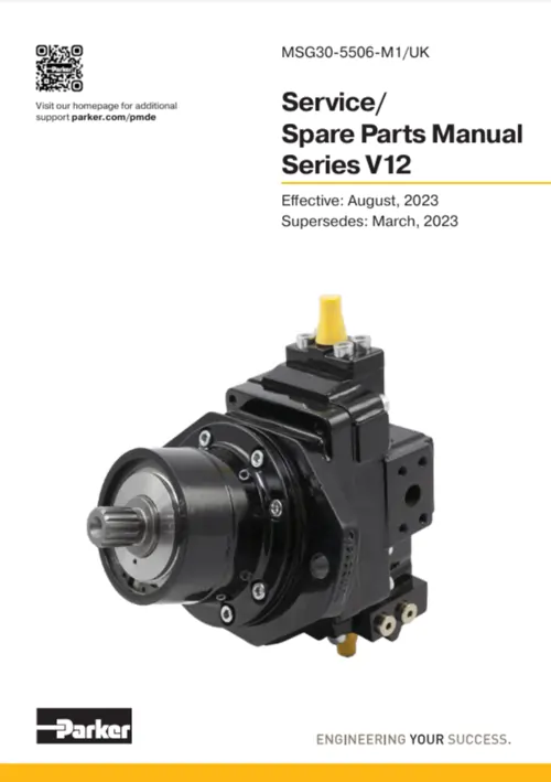
When analyzing different mechanical solutions from various manufacturers, it’s important to consider factors such as durability, efficiency, and adaptability to diverse environments. Each brand offers unique innovations in their designs, often tailored to specific industrial requirements. By comparing these products, one can evaluate their performance and reliability in demanding conditions.
Durability is a key aspect where some providers excel by incorporating materials that withstand extreme pressure and wear. Others focus on lightweight construction without compromising strength, offering better flexibility in application.
Another factor is efficiency. Some models are designed to optimize energy consumption, which can be a deciding factor in long-term operational costs. Comparatively, certain brands emphasize power output, making them suitable for more intensive tasks.
Adaptability to different conditions is where variations are most evident. While some brands specialize in equipment for rough terrains or heavy-duty applications, others focus on compact solutions for precision work in controlled environments.
Upgrading Parker Wheel Motors
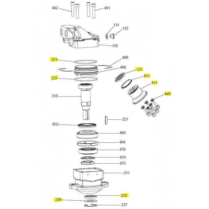
Enhancing the efficiency of these hydraulic units requires careful consideration of performance factors and component compatibility. By selecting modern replacements or optimizing existing mechanisms, one can achieve smoother operation, increased durability, and improved output.
Performance Improvement Strategies: Focus on boosting efficiency by upgrading internal elements like seals, bearings, and hydraulic circuits. These refinements help in reducing wear and tear while maximizing fluid flow.
Maintenance and Customization: Regular upkeep ensures longevity, but customizing key elements to fit specific operational demands can also lead to substantial gains in performance. Tailoring components for higher stress tolerance and temperature control is often recommended.
Future Innovations in Wheel Motor Design
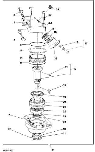
The landscape of rotational drive technology is rapidly evolving, with new advancements on the horizon aimed at enhancing efficiency, performance, and versatility. Engineers are continuously exploring novel materials, refined control systems, and compact configurations to meet the growing demand for more powerful yet energy-efficient mechanisms.
Material advancements are at the forefront of these changes, focusing on lighter, more durable components that can withstand higher stresses while reducing overall system weight. This not only improves the lifespan but also enhances responsiveness and energy efficiency.
Smart systems are another exciting development, with embedded sensors and intelligent controllers allowing for real-time adjustments. These innovations promise to offer smoother operation, self-diagnosis capabilities, and predictive maintenance features, making them more reliable and adaptive to changing conditions.
Lastly, the integration of modular designs paves the way for greater customization and scalability. This shift will make it easier to tailor systems to specific applications, while reducing production costs and simplifying repairs or upgrades.