Maintaining your equipment in good working condition is crucial for ensuring its longevity and performance. Knowing the different elements that make up your machine can significantly aid in troubleshooting and repairs, allowing you to address issues promptly and efficiently.
This guide provides an in-depth look at the various elements of a well-known lawn tractor model. Whether you’re performing routine maintenance or tackling specific repairs, understanding how the pieces fit together will help streamline the process.
In the following sections, we will explore the structure of this equipment, identifying key areas that require regular attention. Equipped with this knowledge, you’ll be better prepared to manage upkeep and resolve issues effectively.
Component Overview for Popular Riding Mower Model
When maintaining a popular riding mower, it’s crucial to understand how various elements come together to ensure smooth operation. From essential engine components to accessories that optimize its performance, knowing what each piece contributes can greatly enhance the longevity of your machine. This section provides a broad look at the key components that make up the mower and how they work in unison.
Engine and Drive System
The core of any mower lies in its power source and drive mechanism. The engine provides the necessary power, while the transmission helps distribute that power to the wheels. Ensuring regular maintenance of these elements is vital for reliable functionality.
- Engine block
- Transmission
- Drive belt
- Axles and wheels
Cutting Mechanism and
Engine Components for Lawn Tractor
The engine of a lawn tractor is a complex system consisting of various interconnected elements that ensure smooth operation and efficiency. Understanding the key components involved in this system helps maintain the machine in good condition and enhances performance over time.
Key Elements of the Engine
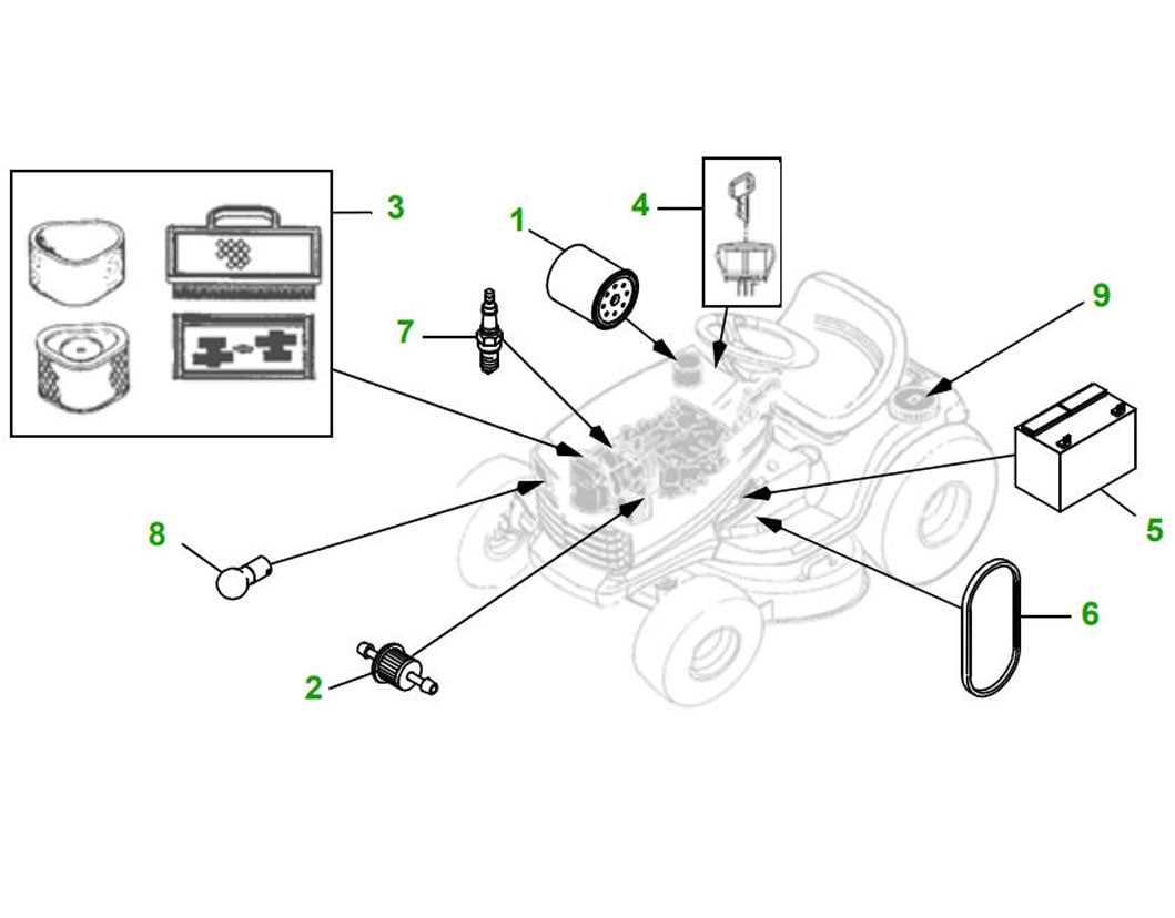
- Air Filter: Prevents dust and debris from entering the engine, ensuring cleaner air intake for optimal combustion.
- Fuel Pump: Responsible for moving fuel from the tank to the engine, ensuring a steady flow for uninterrupted operation.
- Spark Plug: Ignites the air-fuel mixture in the combustion chamber, starting the engine and keeping it running.
Additional Essential Components
- Cooling System: Manages the engine’s temperature, preventing overheating during extended use.
- Oil Filter: Keeps the engine oil free from
Steering System Breakdown
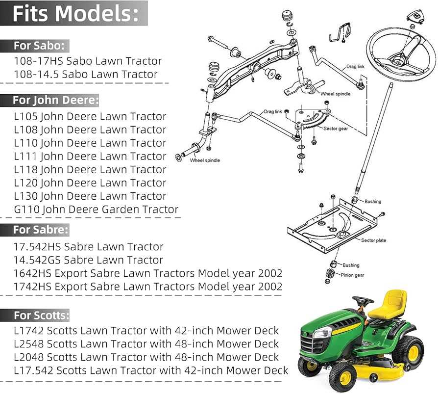
The steering mechanism is a vital part of any machine, ensuring precise control and smooth maneuverability. Understanding how this system works can help maintain proper functionality and ensure long-term reliability.
Main Components
The steering system consists of several key elements that work together to enable accurate control. These include the steering wheel, linkages, and the mechanism that transfers movement to the wheels. Proper alignment and connection between these parts are crucial for smooth operation.
Common Issues
Over time, wear and tear can lead to problems such as loose connections or difficulty turning. Regular inspection and timely replacement of worn elements can prevent larger malfunctions and extend the life of the steering mechanism.
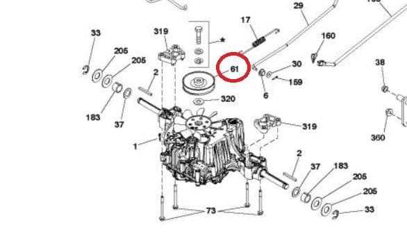
Component Understanding the Transmission Assembly
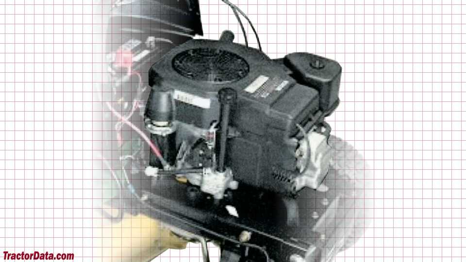
The transmission assembly plays a crucial role in transferring power from the engine to the wheels, enabling movement and control of the vehicle. It is a key system that requires understanding for proper maintenance and troubleshooting.
The assembly consists of several interconnected components that work together to adjust the speed and direction of movement. Each element within the transmission system plays a specific function, ensuring smooth operation and responsiveness under varying conditions.
- Drive Belt: Connects the engine to the transmission, facilitating power transfer.
- Transaxle: Combines the functions of the transmission and axle, allowing for efficient power distribution to the wheels.
- Gearbox: Manages the speed and torque output by adjusting gear ratios according to the vehicle’s needs.
- Linkage: Transmits driver
Detailed Guide to the Electrical System
The electrical system is a crucial part of any modern machinery, ensuring that all the essential functions work efficiently. This section provides an in-depth explanation of the components and wiring involved, helping to maintain the system’s performance and prevent breakdowns. By understanding how electricity flows through the machine, you can better diagnose and address potential issues that may arise.
Main Components of the Electrical Circuit
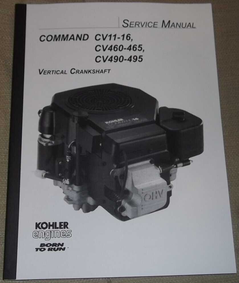
The electrical system is composed of several key components. These include the battery, ignition switch, alternator, and various wires and connectors that work together to power the system. Each part has a specific role, and understanding their interaction is vital for troubleshooting any electrical problems.
Common Issues and Maintenance Tips
Over time, electrical systems may face challenges such as loose connections, worn-out wires, or faulty components. Regular inspections and timely replacement of damaged parts
Front Axle and Suspension Parts
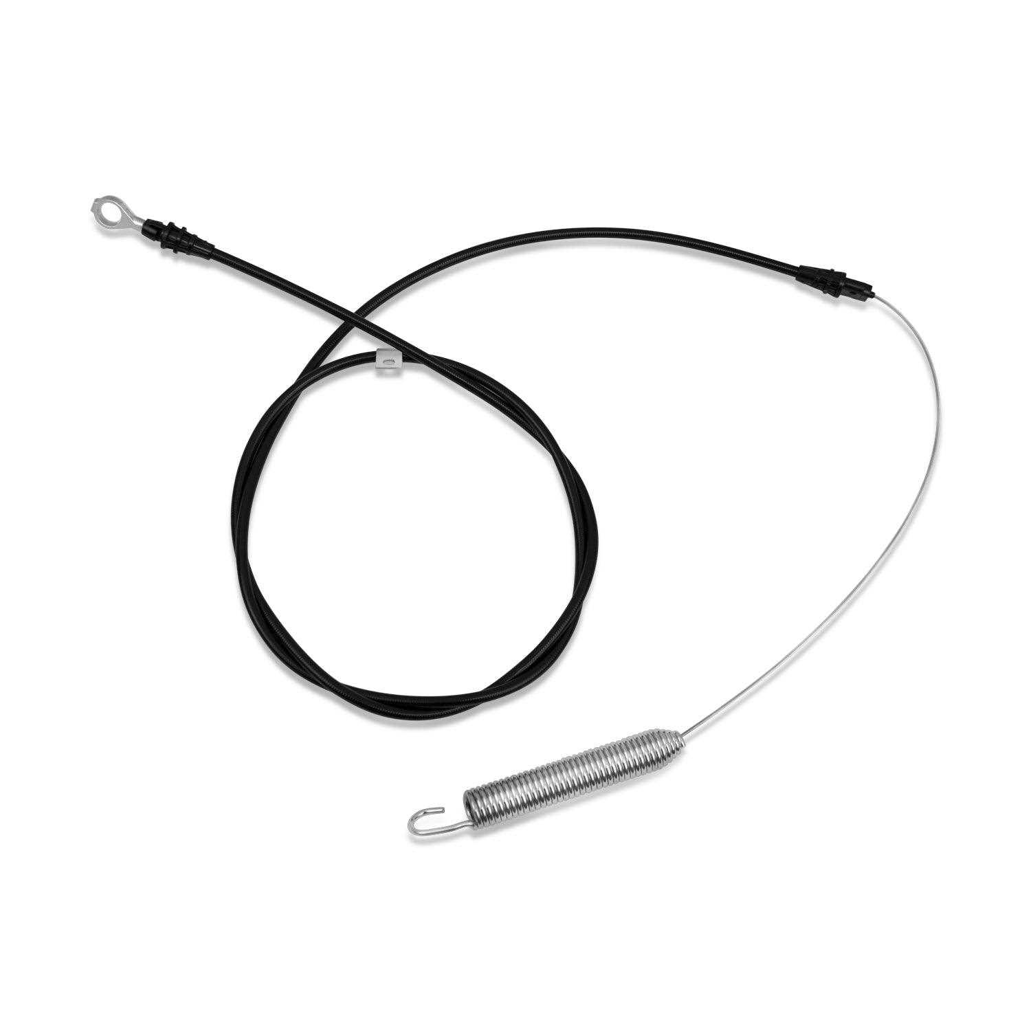
The front axle and suspension assembly plays a crucial role in ensuring stability and control in various terrains. This section will delve into the essential components that contribute to the overall performance and comfort of the machine.
Axle Housing: The main framework that houses the axle, providing strength and support to the structure. It serves as a foundation for other components.
Suspension Springs: These elements absorb shocks and vibrations, enhancing ride quality and maintaining proper tire contact with the ground.
Ball Joints: Critical for connecting various suspension components, allowing for smooth movement while enabling steering control and responsiveness.
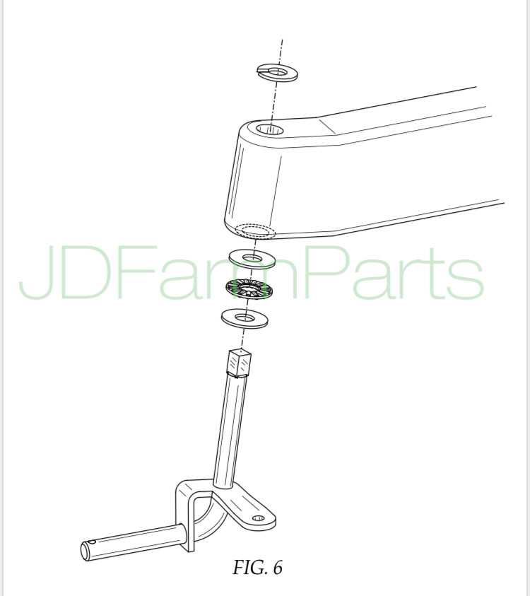
Steering Knuckles: These parts connect the wheel hubs to the suspension system, playing a vital role in steering and handling.
Control Arms: They connect the axle to the frame, facilitating movement and ensuring proper alignment during operation.
Bushings: These are used to reduce friction between moving parts, contributing to a smoother ride and extending the lifespan of the components.
Understanding these elements will help in maintaining the efficiency and longevity of the vehicle’s front axle and suspension system.
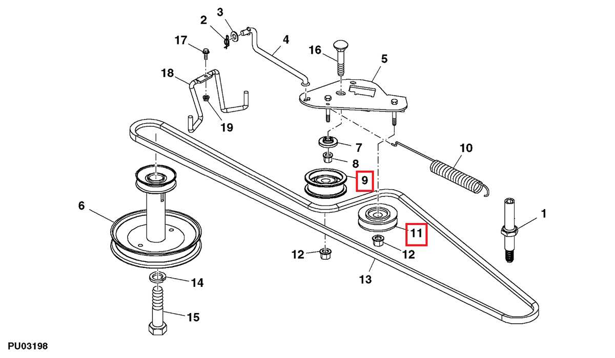
John Deere L110 Deck Assembly Diagram
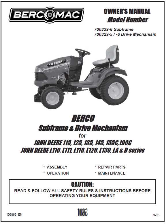
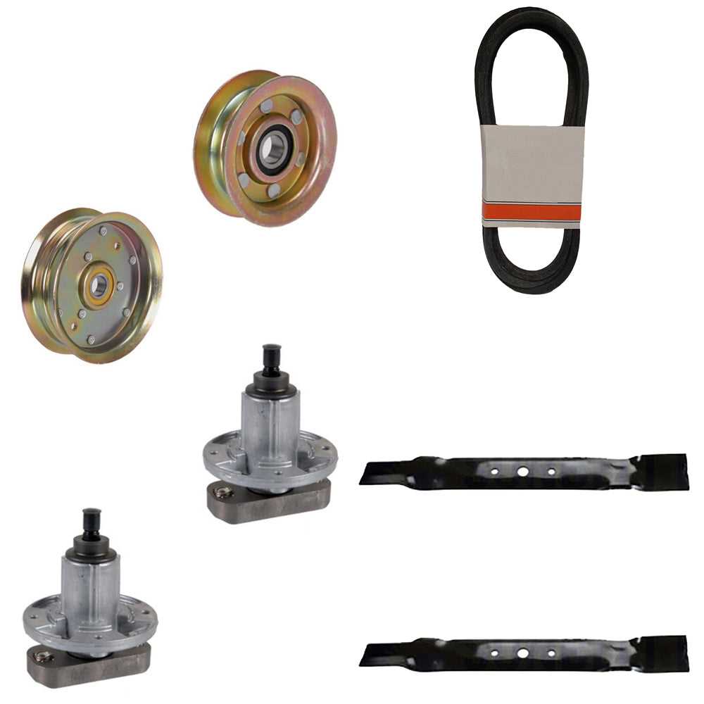
This section provides an overview of the assembly structure for the mower deck, highlighting key components and their functions within the system. Understanding this assembly is essential for proper maintenance and effective operation.
- Cutting Blades: These are essential for achieving a clean and even cut of the grass.
- Deck Shell: The outer casing that houses the blades and protects them during operation.
- Spindle Assembly: Supports the blades and allows them to rotate at high speeds.
- Drive Belt: Transfers power from the engine to the spindle assembly, enabling blade movement.
- Lift Mechanism: Adjusts the height of the deck for various cutting conditions.
- Deck Wheels: Support the weight of the deck and ensure smooth operation over uneven terrain.
Proper installation and maintenance of these components ensure optimal performance and longevity of the mowing equipment. Regular inspections and timely replacements can prevent costly repairs and enhance efficiency.
Fuel System Components Explanation
The fuel system in a garden machine plays a crucial role in ensuring efficient operation and performance. Understanding its components is essential for maintenance and troubleshooting. This section will outline the key elements involved in the fuel delivery and management process.
Key Components
- Fuel Tank: The reservoir that holds the fuel, typically made from durable materials to prevent leaks.
- Fuel Filter: A device that removes impurities and debris from the fuel before it reaches the engine.
- Fuel Pump: Responsible for transferring fuel from the tank to the engine, ensuring a steady flow for optimal performance.
- Fuel Lines: Hoses that carry fuel between the tank, filter, and engine, designed to withstand various pressures.
- Carburetor: An essential component that mixes air and fuel in the correct ratio for combustion in the engine.
Maintenance Tips
- Regularly check and replace the fuel filter to ensure clean fuel flow.
- Inspect fuel lines for cracks or leaks to prevent fuel loss.
- Keep the fuel tank clean and free from contaminants.
- Ensure the carburetor is properly adjusted for optimal performance.
- Use fuel stabilizers to prevent degradation when not in use for extended periods.
Brake System Parts and Functionality
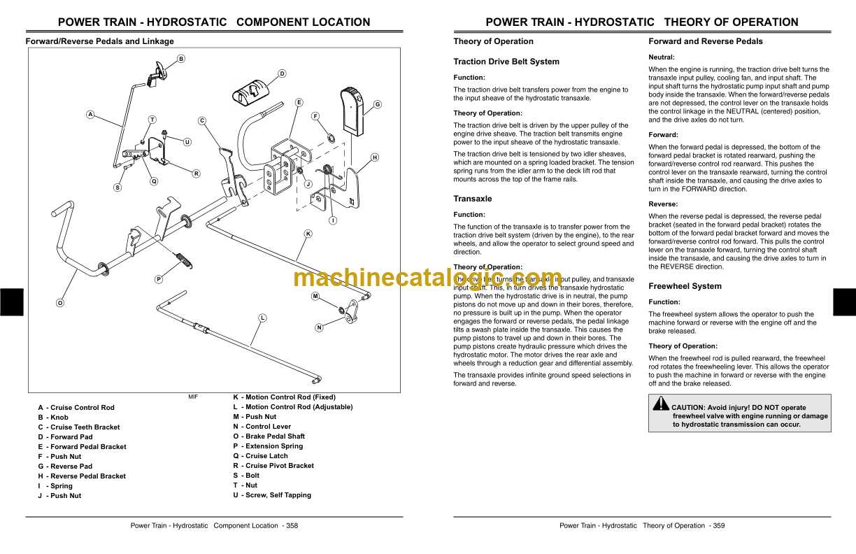
The braking mechanism is a crucial component in any machinery, ensuring safety and control during operation. Understanding the various elements that contribute to its efficiency is essential for effective maintenance and performance. This section delves into the individual components of the braking system and their respective roles in facilitating smooth and reliable braking actions.
Brake Pedal: The brake pedal serves as the primary interface for the operator, allowing for the application of force to engage the braking system. Its placement and design are vital for user comfort and control.
Brake Lines: These conduits are responsible for transmitting hydraulic fluid from the master cylinder to the braking components. Their integrity is essential for maintaining pressure within the system and ensuring responsive braking action.
Calipers: Calipers are pivotal in the braking process, as they house the brake pads and apply friction against the rotors. Their functionality directly influences the effectiveness of the braking system.
Brake Pads: These friction materials press against the rotor to create the necessary stopping force. The quality and condition of the pads play a significant role in overall braking performance.
Rotors: The rotors provide a surface for the brake pads to engage with, converting kinetic energy into thermal energy during braking. Proper maintenance of the rotors is critical to prevent warping and ensure even wear.
Master Cylinder: The master cylinder generates hydraulic pressure within the system when the brake pedal is depressed. This pressure is essential for activating the calipers and achieving effective braking.
In summary, each component of the braking system works in concert to provide reliable stopping power. Regular inspection and maintenance of these elements are necessary to ensure optimal performance and safety during operation.
Wheels, Tires, and Hub Details
Understanding the components related to wheels, tires, and hubs is essential for maintaining optimal performance and safety. These parts play a crucial role in the overall functionality and maneuverability of the equipment. Proper knowledge of these elements ensures longevity and reliability during operation.
Types of Wheels and Tires
Different types of wheels and tires are available, each designed for specific terrains and tasks. Selecting the right combination enhances traction and stability, improving overall efficiency. Here are some common options:
Type Description Standard Wheels Designed for general use, offering a balance between durability and comfort. Off-Road Tires Specialized for rough terrains, providing enhanced grip and resistance to punctures. High-Performance Tires Optimized for speed and responsiveness, ideal for applications requiring agility. Hub Specifications
The hub is a critical element connecting the wheels to the axle, impacting performance and safety. Understanding the specifications of the hub, such as size and compatibility, is essential for ensuring a secure fit and effective operation.
Seat, Body, and Comfort Parts
This section focuses on the various components that enhance the comfort and functionality of outdoor machinery. A well-designed seating arrangement, sturdy structure, and ergonomic features contribute significantly to user experience and operational efficiency.
Component Description Seat Cushion A padded element that provides comfort during extended use, helping to reduce fatigue. Seat Frame The supporting structure that holds the seat in place, ensuring stability and durability. Armrests Side supports that enhance comfort by allowing the user to rest their arms during operation. Backrest A vertical support that offers lumbar support, promoting good posture and comfort. Footrest A platform that allows users to rest their feet, enhancing overall comfort during use. Body Panels External coverings that protect internal components and contribute to the overall aesthetic. Maintenance and Filter Components
Regular upkeep is essential for ensuring optimal performance and longevity of your equipment. This includes the systematic replacement and inspection of various filtration elements that play a crucial role in maintaining efficiency.
One of the key aspects of maintenance involves checking and replacing the air filter. A clean air filter prevents debris and contaminants from entering the engine, enhancing its efficiency. Additionally, oil filters should be routinely changed to keep the lubricant free of particles, ensuring smooth operation.
Fuel filters also require attention, as they safeguard the engine from impurities present in the fuel supply. Neglecting to replace these filters can lead to performance issues and potential damage. Therefore, understanding the specific components involved in the maintenance routine is vital for optimal operation.
Furthermore, keeping track of the maintenance schedule and utilizing high-quality replacement components will help in achieving the best results. Regular inspections and proactive replacements can prevent costly repairs in the future.