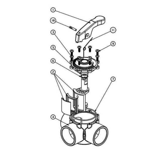
The intricacies of flow control mechanisms play a pivotal role in various systems, ensuring the efficient management of liquids and gases. Grasping the fundamental elements involved in these systems can enhance one’s ability to maintain and troubleshoot them effectively. Each component serves a unique function, contributing to the overall performance and reliability of the mechanism.
In this section, we will explore the essential constituents that facilitate the regulation of flow. By dissecting the functionality of each element, readers will gain insight into how these mechanisms operate and the importance of each part in achieving seamless performance. Understanding these relationships can lead to more informed decisions during maintenance and repairs.
Moreover, having a clear picture of the structure allows for a better comprehension of how to enhance efficiency and address common issues. This knowledge empowers individuals to engage with their systems confidently, fostering an environment of proactive management and problem-solving. Let us delve into the essential components and their roles in optimizing performance.
Understanding Water Valve Components
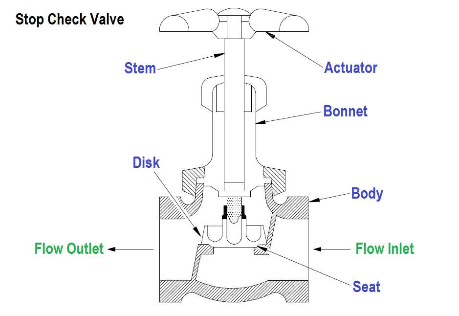
Exploring the various elements involved in controlling fluid flow reveals the complexity and functionality of these systems. Each component plays a crucial role in ensuring efficiency and reliability, facilitating the smooth operation of fluid management in numerous applications.
Key Elements
- Body: The main structure that houses other components, providing the necessary durability and support.
- Actuator: A device that initiates the movement of the mechanism, either manually or automatically.
- Seat: A crucial component where sealing occurs, preventing leaks and maintaining pressure.
- Bonnet: The cover that protects internal components and ensures proper alignment.
- Stem: The part that connects the actuator to the sealing element, allowing for movement and control.
Functionality Overview
- Fluid Control: Each element works together to regulate the flow effectively.
- Sealing: Proper sealing mechanisms are vital for preventing unwanted leaks.
- Durability: High-quality materials are essential for longevity and performance.
- Automation: Advanced systems may include automated actuators for enhanced control.
Understanding these components provides insight into the overall system functionality, ensuring optimal performance and reliability in various environments.
Types of Water Valves Explained
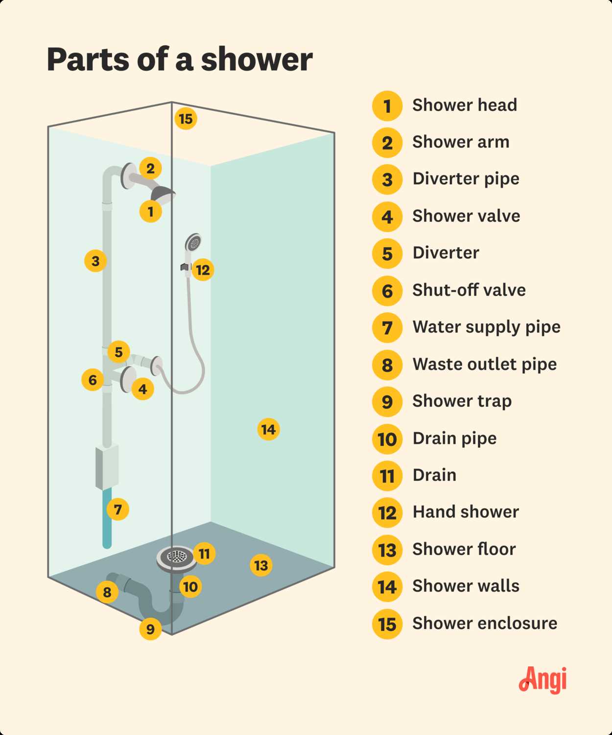
Understanding the different mechanisms that control fluid flow is essential for effective management in various systems. Each mechanism serves a unique function, tailored to specific applications and operational requirements. This section delves into the primary categories, highlighting their characteristics and uses.
Common Mechanisms
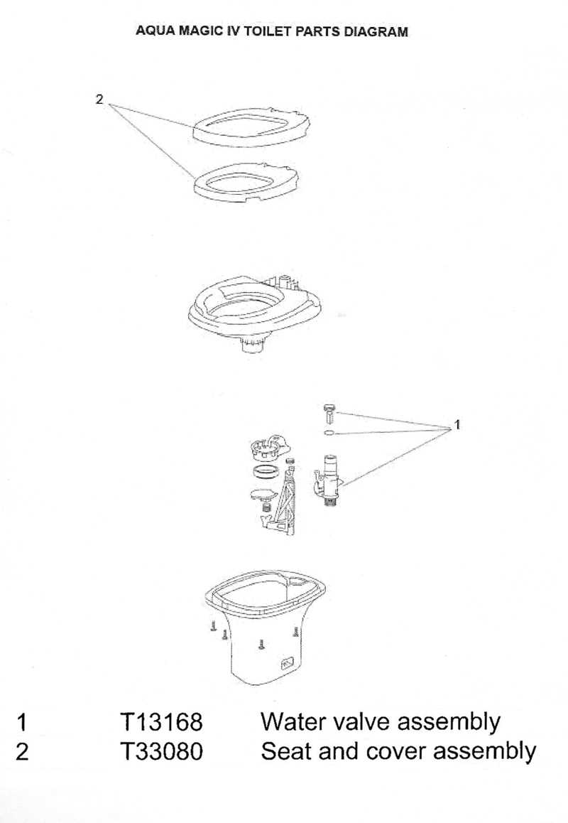
Several types of flow control devices exist, each with distinct operational principles. The most prevalent include those that utilize rotary motion, linear movement, and pressure sensitivity. By examining these categories, one can gain insights into their applications in residential, industrial, and agricultural settings.
Comparison Table
| Type | Operation | Common Uses |
|---|---|---|
| Ball | Rotary | Shut-off applications, quick flow control |
| Gate | Linear | On/Off control, minimal flow restriction |
| Globe | Linear | Flow regulation, throttling |
| Check | Pressure-sensitive | Prevent backflow, maintain direction |
| Butterfly | Rotary | Large flow control, space-saving |
Key Parts of a Water Valve
Understanding the essential components of a control mechanism is crucial for ensuring its proper function and maintenance. Each element plays a specific role in regulating flow and pressure, contributing to the overall efficiency and reliability of the system.
One of the fundamental elements is the actuator, which drives the movement necessary to open or close the flow channel. This mechanism can be manual or automatic, depending on the application. Closely related is the seat, which provides a sealing surface, preventing leaks when the flow is halted.
The disc or gate serves as the primary obstruction that controls the passage of fluid, while the stem connects the actuator to this obstruction, translating motion into action. Additionally, the body of the device houses all components and withstands internal pressures, ensuring structural integrity.
Another vital feature is the handle or control mechanism, which allows for manual operation, providing users with immediate access to adjust flow as needed. Finally, seals and gaskets are critical for preventing unwanted leakage, maintaining the efficiency of the entire assembly.
How to Read a Valve Diagram
Understanding the layout of control mechanisms is essential for effective operation and maintenance. These layouts often include various symbols and notations that convey crucial information about functionality and connectivity. Familiarity with these elements allows for a more intuitive grasp of the system’s design and operation.
Key Elements to Identify
- Symbols: Each symbol represents a specific function or component. Familiarize yourself with standard symbols to interpret the layout accurately.
- Connections: Lines indicate connections between components, showing how fluid flows through the system. Pay attention to the type of lines used, as they may signify different types of connections.
- Labels: Descriptive labels often accompany symbols. These provide important details about pressure ratings, sizes, and operational limits.
Steps to Decipher the Layout
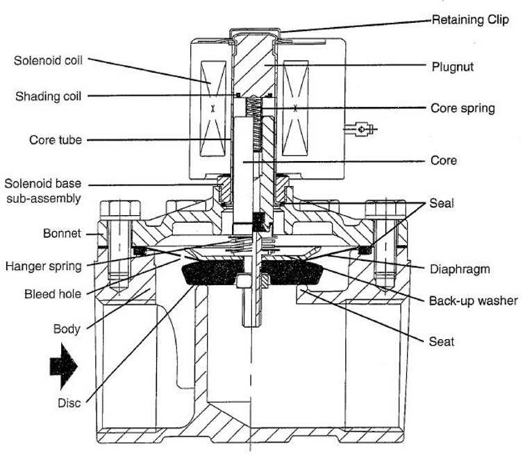
- Start by identifying all the symbols and their meanings using a reference guide.
- Trace the flow direction indicated by arrows or flow lines to understand how components interact.
- Check for any additional notes or legends that explain unique features or requirements of the system.
- Practice interpreting different layouts to enhance your understanding and speed in recognizing various setups.
Common Valve Failures and Solutions
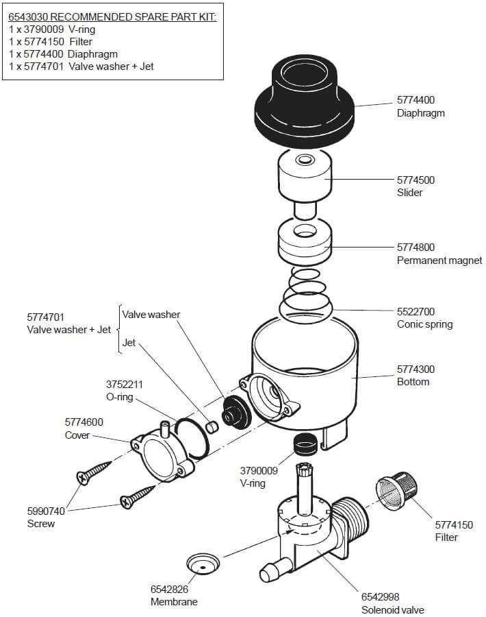
Understanding the frequent issues that arise in flow control mechanisms is essential for maintaining efficiency and preventing costly repairs. This section highlights typical malfunctions, their causes, and effective remedies to ensure optimal performance.
Frequent Issues
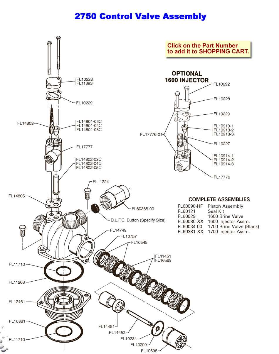
One common problem is leakage, often resulting from worn seals or improper installation. This can lead to reduced pressure and increased operational costs. Another prevalent issue is blockage, which occurs when debris accumulates, hindering fluid flow. Recognizing these malfunctions early can prevent more significant complications.
Effective Solutions
To address leakage, replacing damaged seals and ensuring proper alignment during installation are crucial steps. For blockages, routine inspections and cleaning can help maintain unobstructed flow. Regular maintenance checks and prompt attention to minor issues will enhance the longevity and reliability of the system.
Maintenance Tips for Water Valves
Regular upkeep of flow control mechanisms is essential to ensure their efficient operation and longevity. Proper care can prevent leaks, enhance performance, and reduce the likelihood of costly repairs. Here are some practical recommendations to keep these devices in optimal condition.
| Tip | Description |
|---|---|
| Inspect Regularly | Check for signs of wear, corrosion, or damage to identify potential issues before they escalate. |
| Lubricate Moving Parts | Apply appropriate lubricants to facilitate smooth operation and minimize friction-related wear. |
| Clean Components | Remove debris and sediment from openings and surfaces to maintain proper flow and prevent blockages. |
| Test Functionality | Periodically test the mechanism to ensure it opens and closes correctly without resistance. |
| Address Leaks Promptly | Fix any leaks immediately to prevent further damage and conserve resources. |
| Replace Worn Parts | Identify and replace any components that show significant wear to maintain optimal performance. |
Choosing the Right Valve for Your Needs
Selecting the appropriate control mechanism for your system is crucial for ensuring efficiency and reliability. Different environments and applications require specific features, and understanding these can significantly impact performance and longevity.
Key Considerations
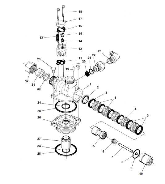
- Application Type: Identify the specific function the device will serve, whether it’s regulating flow, controlling pressure, or managing temperature.
- Material Compatibility: Ensure that the materials used can withstand the substances they will encounter to prevent corrosion and wear.
- Pressure and Temperature Ratings: Check the operating conditions to select a mechanism that can handle the expected ranges.
- Size and Connection Type: Match the dimensions and connection specifications to your existing infrastructure.
- Maintenance Requirements: Consider how often the device will need servicing and choose one that offers ease of maintenance.
Types of Mechanisms
- Ball: Ideal for quick shut-off applications.
- Gate: Best for on/off control with minimal flow restriction.
- Globe: Suitable for throttling flow.
- Check: Prevents backflow effectively.
- Butterfly: Excellent for large volume control with a compact design.
By carefully considering these factors and understanding the various types of control mechanisms available, you can make an informed choice that meets your specific requirements and enhances the efficiency of your system.
Installation Guidelines for Water Valves
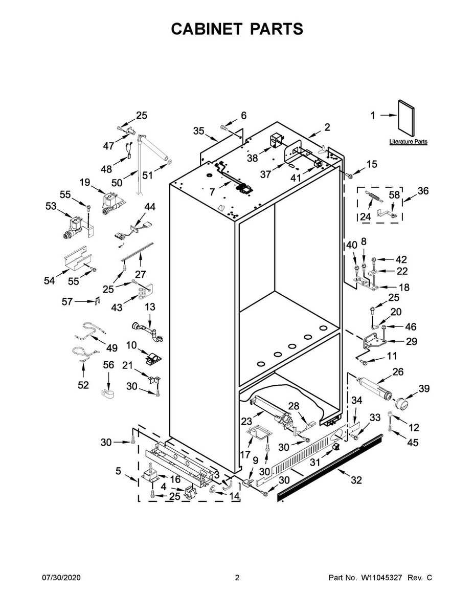
Ensuring the proper setup of flow control mechanisms is essential for optimal functionality and longevity. This section outlines key considerations and steps necessary for a successful installation, promoting efficiency and minimizing potential issues.
Before beginning the installation process, it is crucial to gather all necessary tools and components. Proper preparation will facilitate a smooth and effective setup. Follow these guidelines for a successful installation:
| Step | Description |
|---|---|
| 1 | Turn off the main supply to prevent any leaks or pressure buildup during installation. |
| 2 | Inspect the installation site to ensure it is clean and free from debris that could obstruct the connection. |
| 3 | Align the mechanism correctly with the existing piping, making sure to follow the manufacturer’s specifications. |
| 4 | Secure the connections tightly, using appropriate sealing materials to prevent any leaks. |
| 5 | Once everything is connected, gradually restore the main supply and check for any signs of leakage or malfunction. |
Following these steps will help ensure a reliable and efficient setup, contributing to the overall performance and durability of the system.
Safety Precautions When Handling Valves
Ensuring safety during the handling of mechanical components is crucial for preventing accidents and ensuring operational efficiency. Proper awareness and adherence to safety measures can significantly reduce the risks associated with maintenance and operation. This section outlines essential guidelines to follow for safe management of these critical elements.
Understanding Potential Hazards
Before engaging with any mechanism, it is vital to recognize the potential dangers that may arise. Exposure to high pressure, sudden leaks, or sharp edges can lead to serious injuries. Always inspect the area for any signs of wear or damage, and ensure that you are equipped with the appropriate personal protective equipment (PPE) such as gloves and goggles.
Proper Handling Techniques
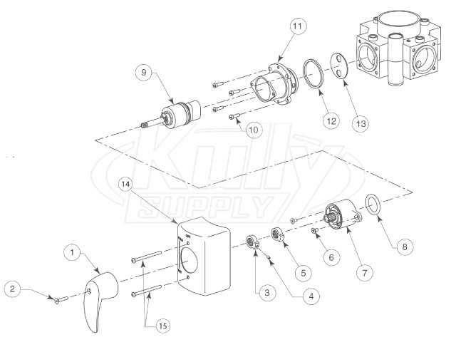
When working with these components, utilize correct handling techniques to minimize risks. Always secure the device before beginning any maintenance. Employ tools designed for specific tasks to avoid unnecessary strain or accidents. Moreover, it is essential to follow the manufacturer’s guidelines and safety protocols, ensuring that every action taken promotes a safe working environment.
Innovations in Valve Technology
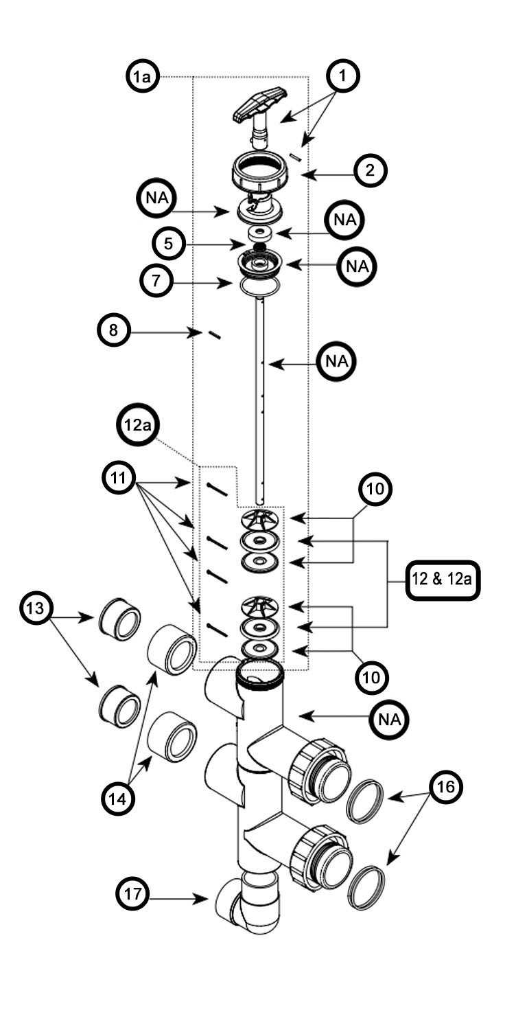
The evolution of control mechanisms in various industries has led to groundbreaking advancements, enhancing efficiency and reliability. These improvements are crucial for optimizing processes and meeting the growing demands of modern applications.
Recent developments include the integration of smart technologies, which allow for real-time monitoring and automation. Such innovations facilitate predictive maintenance and reduce downtime, ultimately leading to cost savings and improved performance.
Another significant trend is the use of advanced materials that enhance durability and resistance to harsh environments. This shift not only extends the lifespan of components but also ensures consistent operation under varying conditions.
| Innovation | Description |
|---|---|
| Smart Technologies | Integration of IoT for real-time data monitoring and automated control. |
| Advanced Materials | Utilization of high-performance materials for increased durability and resistance. |
| Energy Efficiency | Design improvements aimed at reducing energy consumption during operation. |
| Modular Design | Flexible systems that allow for easy upgrades and customization. |
As industries continue to evolve, these advancements not only enhance operational capabilities but also contribute to sustainability goals, making them vital for future developments.